MIMO and beamforming provide increased data rates than you can get using single, omnidirectional signals.
Antennas convert between radio waves propagating through space and electric currents moving in a metal conductor. In early communication system, antennas were often quite simple, perhaps just a half-wave dipole constructed of wire. We usually just had one antenna per radio, used for both transmit and receive. As wireless communications have advanced, wireless engineers have figured out how to deploy multiple antennas in a wireless system to improve performance. Two main technology trends, MIMO systems and phased-array antennas, transmit and receive the radio signals needed for 5G.
Multiple Input Multiple Output (MIMO)
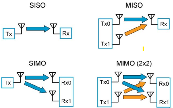
Figure 1 shows four configurations of transmit and receive antennas. The basis system of one antenna on each device is known as Single Input Single Output (SISO). This is the simplest and most common antenna configuration for a wide variety of radio uses. Add a second transmit antenna and you get Multiple Input Single Output (MISO). Put the second antenna on the receiver and you have Single Input Multiple Output (SIMO). Finally, with multiple antennas on both the transmitter and the receiver, we have Multiple Input Multiple Output (MIMO), which is the configuration we will focus on.
Figure 1. These four common radio configurations may be used in wireless communications systems. Image: Keysight Technologies.
For simplicity, Fig. 1 shows just two antennas on each device (called 2×2 MIMO). This method has been extended to use many more antennas. For example, WiFi-6 uses up to 8×8 MIMO and 5G will add even more antennas.
Spatial Multiplexing
MIMO takes advantage of spatial multiplexing to increase a channel’s the bandwidth without consuming additional spectrum. This sounds like an impossibility, but the technique actually works. Many wireless channels experience multipath propagation, which occurs when the radiated signal follows multiple paths to go from the transmitter to the receiver. A common mechanism for these multiple paths is reflection of the radio signals off mountains, buildings or other obstructions.
In SISO radio systems, multipath propagation often causes distortion at the receiver when multiple signals recombine. Having traveled different paths, these signals are skewed in time and thus add destructively, introducing distortion. MIMO takes advantage of this channel characteristic by using these alternative paths to send addition information. The more multipath that exists, the better the throughput using MIMO. Indeed, if multipath propagation is not present, MIMO loses its advantage and performs similar to a SISO system.
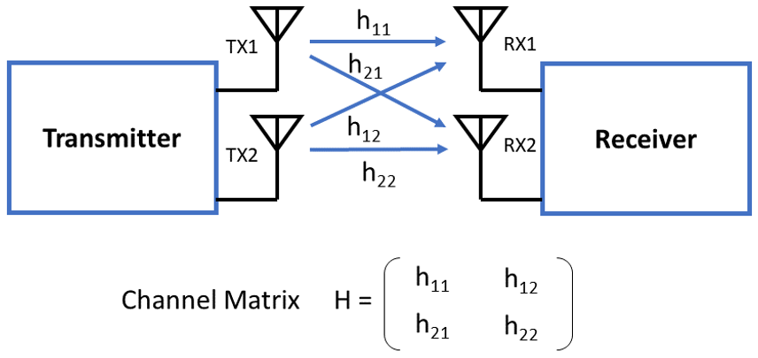
The signal processing required to implement MIMO is extraordinarily complex. Figure 2 shows a simplified model of the channel matrix H, for a 2×2 MIMO system. The channel matrix describes the channel characteristics in matrix form for each of the transmitter/receiver pairs. Knowing or at least estimating these channel parameters lets a MIMO system exploit the multipath propagation.
Figure 2. The channel matrix mathematically describes the signal paths between all MIMO antennas. Graphic by Bob Witte.
The channel matrix is also referred to as Channel State Information (CSI), the known channel properties of a communication link, including scattering, fading, and power attenuation with distance. Some MIMO systems are open loop, requiring the receiver to estimate the channel matrix. More advanced systems use feedback from the receiver to inform the transmitter about the CSI.
Ideally, the CSI is updated in real time because the channel characteristics can change quickly. Devices in the system may be moving and obstacles between the transmitter and receiver may appear and disappear. Ideally, CSI is a complete and accurate characterization of the path from every transmit antenna to every receive antenna. In practice, it is less than this due to limited feedback, changing channel conditions and error in the measurement.
Beamforming
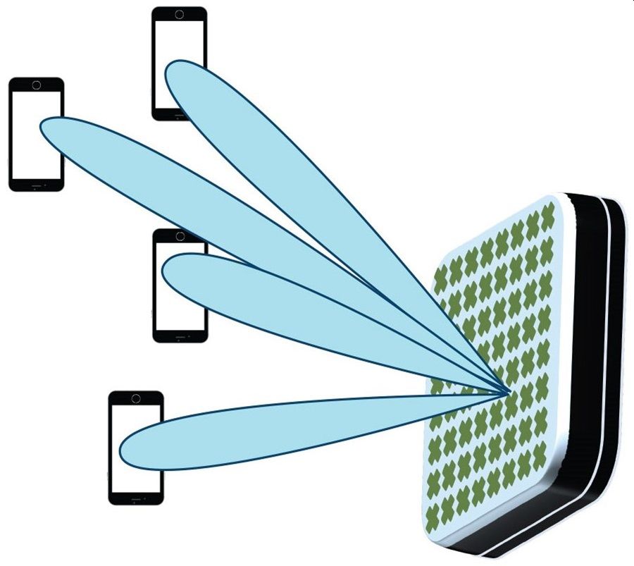
So far, we have assumed the use of simple antennas that have a broad radiation pattern. Another technology trend in wireless communications is the increased use of phased-array antennas (Figure 3). Phased-array antennas consist of numerous antennas independently controlled and combined to create a specific antenna radiation pattern. By adjusting the signal’s amplitude and phase delivered to each individual element of the antenna, the combined signal can be maximized in the desired direction. The term “beamforming” is used to describe this use of phased-array antennas. (Also, the term “beamsteering” refers to the dynamic control of the beam to optimize system performance.)
Figure 3. Phased-array antennas steer signals to desired directions by adjusting amplitude and phase. Image: Analog Devices.
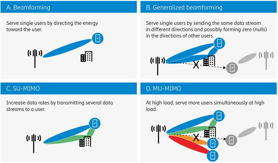
With a phased-array antenna, we can steer the signal where we want it to go, for maximum effectiveness. Figure 4A shows a wireless system with a base transceiver station (BTS) talking to a single user equipment (UE). The BTS uses beamforming to maximize the signal to that UE (basic beamforming). Fig. 4B shows the more generalized case with the BTS sending out multiple lobes to optimize the signal to the UE while creating a null towards another UE in an adjacent cell. Here we see that the antenna radiation pattern can have multiple lobes and notches.
Figure 4. Beam steering can range from using a single antenna/receiver pair to a cell tower handling many user equipment. Image: Ericsson.
MIMO and beamforming can be combined for greater effect, as shown in Fig. 4C. The antenna pattern can be adjusted to optimize the multipath propagation exploited by MIMO. The system in Fig. 4C shows one UE being served by the BTS, so this is called single-user MIMO (SU-MIMO). Fig. 4D shows a multi-user scenario (MU-MIMO) with multiple antenna lobes serving different UEs. There may also be nulls in the pattern to reduce interference from UEs in nearby cells. Clearly, this MU-MIMO scenario can result is a complex antenna radiation pattern to support all the UEs. Keep in mind that the UEs are typically in motion, so the BTS needs to make adjustments in real time.
Fig. 4 is drawn with the focus on the BTS transmitting to UEs (the downlink). There is a corresponding challenge on the uplink side, where the UE must transmit back to the BTS.
Summary
MIMO is all about spatial multiplexing, taking advantage of the multiple paths in the channel to improve the data throughput. Beamforming is an additional technique that can uses phased-array antennas to improve system performance, with or without MIMO. Together, these two techniques squeeze the maximum performance out of a wireless channel.
References
-
- ”Beamforming & Beamsteering Antennas,” Electronics Notes, https://www.electronics-notes.com/articles/antennas-propagation/smart-adaptive-antennas/beamforming-beamsteering-antenna-basics.php
- “The difference between active and passive antenna systems”, Majeed Ahmad, 5G Technology World, Mar 3, 2020, https://www.5gtechnologyworld.com/the-difference-between-active-and-passive-antenna-systems/
- “Advanced antenna systems for 5G networks,” Ericsson white paper, GFMC-18:000530, November 2018. https://www.ericsson.com/en/reports-and-papers/white-papers/advanced-antenna-systems-for-5g-networks
- “Advanced Antenna Systems For 5G,” 5G Americas White Paper, August 2019, https://www.5gamericas.org/advanced-antenna-systems-for-5g/
 Bob Witte is President of Signal Blue LLC, a technology consulting company. Bob has held many positions in R&D, technology planning, strategic planning, and manufacturing for Keysight Technologies, Agilent Technologies and Hewlett-Packard Company. Inside, he is just an engineer that loves to see innovative products solve real customer problems. Bob is the author of two books on test and measurement instrumentation: Electronic Test Instruments (2nd Edition) and Spectrum and Network Measurements (2nd Edition).
Related articles
- The basics of 5G’s modulation: ODFM
- What’s All This 5G Stuff, Anyhow?
- Massive MIMO performance testing: Emulate the channel
- How to Test 5G: From Millimeter-Wave to Massive MIMO to Beamforming
- 5G Over-the-Air Testing: An update

