My previous blog touched on peak detect circuits. What seems simple in principle can be quite problematic if you want speed and accuracy. A diode and a capacitor makes a crude peak detect but the voltage drop of the diode makes it a poor choice so you will normally add an opamp to improve accuracy.

You would typically add a buffer to prevent loading the capacitor, but for now we will omit that. This sort of circuit will work reasonably well with a slowly changing input:
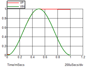
However, if you have a pulse input it isn’t so good.

The voltage across the capacitor (the output – red trace) overshoots the input (green trace). I have included the opamp output on this plot as it helps to illustrate where it goes wrong. The limited speed of the opamp means that it cannot respond quickly enough when the inverting and non-inverting inputs are at equal voltages so the opamp output keeps rising after VP reaches VIN. This produces the overshoot you can see in the output. Note that the opamp output is expected to go above the input voltage because it has to also overcome the diode forward volts drop.
There are circuits you will come across which add a second opamp to prevent the opamp going very negative once the capacitor has charged in order to improve the speed of detection of subsequent peaks. By limiting the amount the opamp output goes negative it speeds up the “topping up” of the capacitor charge. However, it doesn’t solve the fundamental problem of overshoot and in fact makes it worse (by adding another opamp delay in the loop).
One solution to the overshoot is to add some resistance:

The waveforms from that circuit are shown below. The peak detect isn’t as fast now – the additional resistance slows it down, but it also makes it more stable. If the opamp doesn’t like much load capacitance (and most don’t like capacitance) then it also helps to prevent instability caused by the reduced phase margin from the load capacitance.

The green trace shows the voltage across the capacitor which has almost no overshoot. You need to choose the resistor to be large enough to prevent overshoot but not so large that it makes the circuit too slow for your needs.
How about if you need a faster peak detect? Faster opamps are one solution. Unless you have a CMOS front end opamp then you will have some droop (or unwanted capacitor charging) due to the input bias current. Normally that can be tolerated and you just need to design your circuit and choose the peak detect capacitor to hold the voltage long enough for you to read the value with the desired accuracy.
One technique to create a fast peak detect for short pulses is to use a cascade of two or three peak detects with the first often being a fast bipolar one, and therefore droopy due to base current. Subsequent peak detects can then store the peak from the previous one and can be slower and hence have lower bias current. It tends to make more economic sense as a custom integrated circuit solution, or with discrete transistors rather than using a cascade of opamps.
The circuit you will find for solving the problem of the opamp output being in negative saturation between pulses is shown below.

However, as mentioned earlier, it is actually worse for overshoot with fast input pulses because of the additional delay from the second opamp. The benefit of this circuit is that R2/D2 prevents the inverting input of the first opamp from going very negative so when a new pulse comes along it is not as limited by slew rate as it could otherwise be. However, it suffers from even more overshoot than the simpler circuit and again benefits from the addition of resistor in series with the capacitor.

While this significantly improves the performance by preventing overshoot, the output you need is really the capacitor voltage so you will need another buffer. You can use the output of the second opamp shown but it will have a small transient overshoot, although the value shortly after the peak will be correct. The plots below compare the two dual opamp circuits:

The overshoot without the additional resistor is quite evident (green trace). You need to know the nature of your input signal if you are considering the dual opamp system. If your input voltage returns to zero after each pulse and you have a reset mechanism after each pulse, there is no benefit in the dual opamp circuit – the first opamp output will still have to follow the input pulse from zero volts. You would be better with a single opamp circuit and include an appropriate resistor with your capacitor – it will be a faster circuit.


Leave a Reply
You must be logged in to post a comment.