The power management IC (PMIC) is often a vital part of the lower-voltage DC subsystem, as circuits have multiple power rails with tight individual specifications as well as mandated relationships among them.
It’s one thing to develop needed low-voltage DC rails via DC/DC converters or regulators, but there’s also a need to manage these power rails in many system designs. This is increasingly the case as systems and even individual ICs have power rails with requirements for their own nominal DC value as well as for ramping up/down timing and other attributes. The solution is to use a power management IC (PMIC) to manage a single rail, and then extend that to the relationship and interaction among multiple rails.
Q: What functions can a PMC provide?
A: There is no official or formal definition of a PMIC’s function, and the answer varies with the vendor and the situation. In general, a PMIC can do one or more of the following: actual DC/DC conversion/regulation; battery charging and management; power-source selection; power-rail sequencing; and power-rail ramp up/down timing. We’ll focus on the sequencing and timing functions in this FAQ, Figure 1.
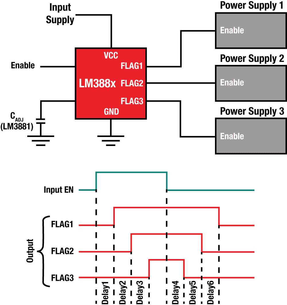
Fig 1: The LM3881 PMIC from Texas Instruments is a basic 3 rail, simple power sequencer with adjustable time delay. (Image source: Texas Instruments)
Q: Is the PMIC a separate IC?
A: It depends. In some cases, some or most of the PMIC functions are embedded in the power-related IC, such as a DC/DC regulator, and sometimes they may be in the load that the rails are supplying. In other cases, the PMIC is a distinct IC and operates independent from the other power-related ICs. If the PMIC functions are embedded in the larger IC, some other power-management functions may need to be provided for other rails and functions of the system, so a separate PMIC may still be needed. Note that PMIC functions are not only for larger ICs and systems, as even a small ICs such as an op amps with multiple supplies may need sequencing (see Reference 1).
Q: It’s still not clear why a PMIC is needed; can you tell me more?
A: Today’s circuits often have more than one DC rail; even a single IC such as an FPGA may have four, five, or more rails of different voltages, or even with the same nominal voltage but for different sub-functions within the ICs (so they can be disabled to save power, or to meet I/O needs). In most designs, it is critical that the turn-on/turn off sequence of these multiple rails be done in a specific, defined order, so that one (or more rails) be at full voltage (or at least some pre-set value) before turning on another rail; in some cases, the turn-off sequence is also important. In addition, the rate of rise/fall (rise time/fall time) for these rails may be critical as well.
Q: Is power sequencing a new development in electronics?
A: No, it is not; for example, it has existed since the early days of larger vacuum tubes, where the electron-emitting filament (cathode) had to be fully heated before the plate (anode) could be turned on. This could take anywhere from a few seconds to several minutes and was either done by hand or automated with interlocked relays and timers; now, it is done with a processor-based system such as an Arduino board (see Reference 2).
Q: Does the PMIC also provide circuit-protection functions such as power good, overvoltage protection, undervoltage lockout (UVLO), crowbars, surge protection, and more?
A: Generally not, as those functions require capabilities and processes which may not be compatible with ICs. Further, in many cases, the power-related IC or function (not the PMIC) provides these functions so they would be redundant if in the PMIC. However, the UVLO function is, in effect, implemented by the PMIC since that IC identifies the “power good” and UVLO as part of the sequencing process.
Q: How is are PMIC functions and relationships established?
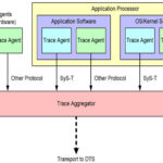
A: There are PMIC devices which are preset with the relative timing and relationship among the various rails, with some flexibility. Other are more fully user programmable, often via an I2C or PMBus interface, to allow the user to set the specifics of the sequencing and other parameters that the PMIC is managing. In some cases, a few external cents such as resistors or capacitors may be needed by the PMIC. In very complicated systems, a dedicated microcontroller may be used with the sole task of providing PMIC functions, Figure 2.
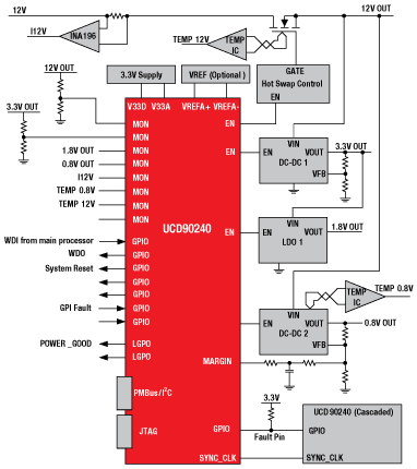
Fig 2: For advanced, complex applications, the Texas Instruments UCD90240 24-rail PMBus power sequencer and power manager offers many features and extreme flexibility in how the rails are set up, interact, and report status. (Image source: Texas Instruments)
Q: How does the PMIC actually control the power rails?
A: Usually, it is done via a simple, low on-resistance MOSFET placed between the rail source and the load. The PMIC controls this MOSEFT and thus its resistance, similar to a load switch (see References 3 and 4). The PMIC manages the turn-on/off rate and timing via these MOSFETs, one per rail.
Q: Are there different PMIC timing strategies and sequences?
A: Yes, there are three basic types of timing – sequencing, ratiometric, and simultaneous – as well as variations of each:
–In sequential timing (Figure 3), the second rail turns on only after the first one has reached its nominal regulated value;
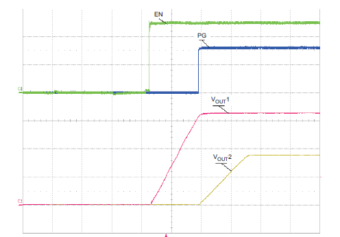
Fig 3: In sequential timing, the second rail begins its turn-on ramp-up after the first rail has reached its target voltage. (Image source: Texas Instruments)
–In ratiometric timing (Figure 4), both output voltages start at the same time and both voltages reach regulation at the same time; it is called “ratiometric” since the two voltage are usually different, so their dV/dt slopes differ but are related by a constant factor.
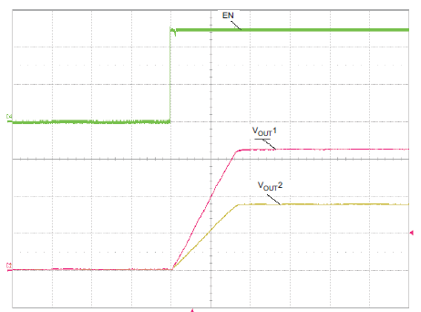
Fig 4: For ratiometric timing, the output voltages start at the same time and reach regulation at the same time; thus, their rate-of-rise slopes differ but with a constant multiplier between them. (Image source: Texas Instruments)
–Finally, in simultaneous start-up (Figure 5) the slopes of both output voltages are the same; thus, both voltages reach regulation at different times.
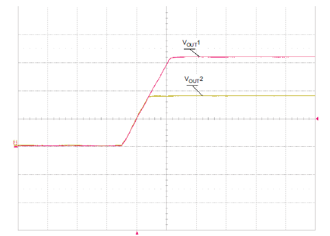
Fig 5: Just as the name indicates, in a simultaneous start up, the ramp-ups start at the same time and have different slopes; thus, they each reach their nominal value at different times. (Image source: Texas Instruments)
Q: Is a dedicated PMIC needed to manage basic sequencing?
A: Not necessarily. Some DC/DC regulators have extra pins for enable and sequencing, such that there relative timing can be hardwired. This saves cost and board space as no separate PMIC is needed, but may limit the flexibility that is available (but perhaps not needed). The tradeoffs must be considered by the designer and power-rail objectives.
Part 1 of this FAQ has looked at the basics of power-rail management via PMICs or other options. Part 2 will look at some specific PMIC devices and implementations.
References
- Analog Devices, “Improper Power Sequencing in Op Amps: Analyzing the Risks“
- Audio Express, “Arduino-Based Tube Power Amplifier Controller”
- EEWorld Online, “Load switches, Part 1: Basic role and principle”
- EEWorld Online, “Load switches, Part 2: IC implementations and benefits”
- Texas Instruments, SLVA470, “Sequencing and Tracking With the TPS621-Family and TPS821-Family”
- Analog Devices, LTC3676 Data Sheet


Leave a Reply
You must be logged in to post a comment.