A number of systems I have developed have required the processing of pulsed analog signals. Depending on the system, one or more attributes of the signal needed to be preserved and measured such as pulse height, pulse width, pulse shape and pulse position in time. Also, you usually need some gain to boost the signal and filtering to prevent spurious signals from affecting results. Higher speed, high-resolution ADCs and processors have resulted in some applications using digital processing as much as possible – digitizing the incoming signal as fast as possible and measuring the required attributes and filtering noise in the digital domain. However, the level and speed of the signals may make that impractical. Also, a lot of high-speed processing can be quite power hungry for battery operated systems.
So, what should you watch out for when trying to process pulsed signals? It depends on the nature of your pulse to begin with and what attributes of it are important to you. While a theoretical pulse might look like the red trace below, you are more likely to be faced with a pulse shaped more like the green trace.
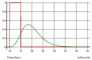
What may have started out as a symmetrical pulse may be asymmetrical like the green trace, even after minimal processing and may be due to your sensor. As I have mentioned in previous blogs, choosing the right filter is essential for preserving shape. The shape of a pulse is due to a combination of many frequencies which make up any non-sinusoidal waveform. If you delay some frequencies more than other or attenuate some frequencies more than others then you will alter the shape. Unfortunately if you want to filter out noise you want to attenuate some frequencies and not others so some shape alteration is inevitable. What you need to ensure is that you know the extent of any shape change and how it will affect the accuracy of the parameter you are trying to measure.
In some cases the original pulse shape will be well known so if you also know the effect your signal processing has had on the original signal you can work back to what the original signal was in order to compensate for signal processing effects. For example, if you know that your filter delays signals by 10µs and you want to know when the pulse actually happened, simply subtract 10µs. If you want to know the pulse width (e.g. FWHM full width at half maximum) and you know that you filtering adds an extended tail to the pulse, you can compensate for that.
Your circuitry could be AC coupled (i.e. high pass filtered) which brings its own set of problems. The graph below shows what happens when you AC couple the green pulse with the result shown in blue.

The amount of negative undershoot (and resulting loss of peak amplitude and reduction in FWHM) can be reduced by reducing the low frequency cut-off point of the AC coupling. However, often AC coupling is used to compensate for other undesirable effects which would otherwise be moving the baseline up and down, affecting peak pulse measurements. This baseline shift can be one of the trickiest pulse processing problems to solve, particularly in systems where the size and spacing between pulses is variable. There will also be the potential for corrupted signals in such cases, where two separate pulses are close enough to interfere with one another making a pulse width or amplitude measurement difficult. In medical and other systems I have worked on which potentially suffer from such problems it can usually be tolerated, because the final result is a statistical result from many pulses so an occasional rogue pulse does not invalidate the overall measurement.
I have used baseline recovery circuits and seen them used in other systems. For example, every time you detect a pulse you can then clamp the signal to your zero reference to reset it. Anyone familiar with analog video signals will know this as an operation carried out in the “back porch” – a specific portion of each video line used to reset the black levels of an AC coupled signal. In the case of a video signal, the waveforms are designed with the signal processing in mind. You know exactly when to do your clamping relative to the line sync signal. For an instrument such as an ionizing radiation spectrum analyzer you would have to devise your own method of determining when to reset the signal.
There are methods of AC coupling whereby an integrator is used to feed back the output error in a DC coupled circuit. This sort of circuit is shown below, from the INA128 data sheet.

This sort of circuit is mainly used with instrumentation amplifiers and the integrator feedback applied to the common mode reference point. It provides a means of giving the effect of AC coupling without putting capacitors in series with the signal, which would be tricky with high impedance inputs. The effect is identical to true AC coupling so won’t solve a baseline shift problem – it will still shift.
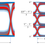
However, any sort of AC coupling is a potential problem with a pulsed system because the baseline will move based on the incoming pulse width and repetition rate. For example, a 10% duty cycle negative going pulse will shift the baseline by 10% as shown below.

If you are measuring pulsed signal amplitude you will not be wanting such a baseline shift so some sort of correction will be required, either digitally or electronically. A “mixed signal” approach could be used where you correct for the baseline shift after digitizing, assuming that you are digitizing the signal.
Another alternative is to use peak detect circuits. You could use a negative peak detect to correct for the baseline shift (in a system with positive going signals) and a positive peak detect to measure amplitude. A positive and negative peak detect could be used to feed the differential inputs of an ADC without actually correcting for the baseline shift – simply measuring it. Peak detect circuits are a problem for a later blog. At low speeds they are fine but as the speed increases they become increasingly problematic.


Leave a Reply
You must be logged in to post a comment.