Rather than a physical switch it is now common to use “touch” switches to interface to many types of electronic equipment. Smartphones are an obvious example but touch switches are now in cars, oscilloscopes, ovens and many other types of industrial and consumer electronics. A touch screen will usually be a specialized screen with a capacitive or resistive surface for detecting touch, but for interfacing just a few “buttons” you will probably use a different approach. For example, a few metallic areas behind a plastic or glass panel could be all that is required to provide a user interface to your microcontroller.
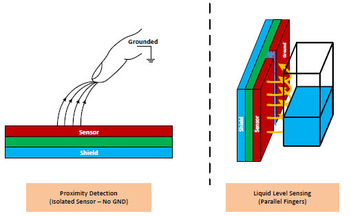
There are two types of capacitive “touch” switching which are usually called touch detection and proximity detection. With touch detection, the operator’s finger is adding to the capacitance of a parallel plate capacitor. It will detect a few millimeters from the touch plate which is useful if you want it to be behind glass or plastic. Proximity detection relies on the operator disturbing the fringe capacitance of a capacitor, and that can work over much larger distances. The Texas Instruments Application Report SNOA927 explains this, in relation to their FDC1004 sensor IC.
You can make your own capacitive touch interface using a simple circuit that detects capacitance. Timing how long it takes to charge or discharge the capacitor with a fixed resistance or current is one method. Using the touch capacitance as part of a resonant circuit is another. A proprietary chip will usually help to overcome some of the potential problems with touch switches such as the stray capacitance, changes in stray capacitance from contamination, temperature, and environmental changes as well as immunity from interference. If you make a very simple capacitive detector then you will need to solve those sorts of problems in your own software, assuming you have a microcontroller based system.
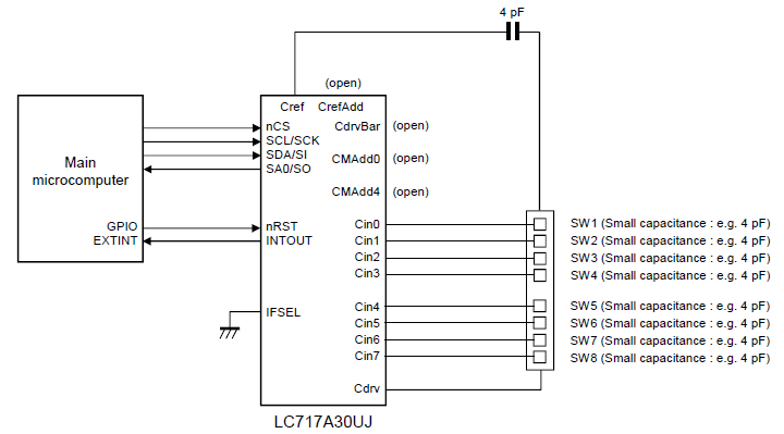
A chip such as the ON Semiconductor LC717A30UJ provides a capacitive touch switch interface with up to 8 inputs and I≤C and SPI interfaces. It only provides an on/off interface for each input. Depending on the setup it can be used for touch or proximity based sensing. With proximity based sensing the user’s finger will be detected from further away than “touch” sensing, provided your touch pads and ground are appropriately designed.
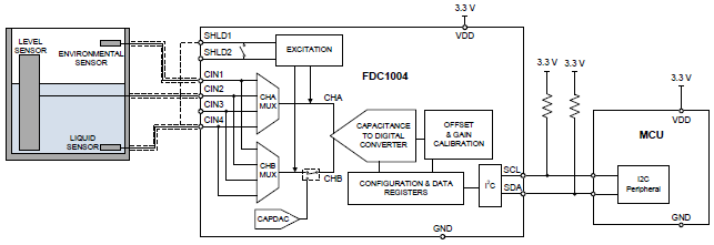
Some devices provide a digital value output rather than simply a binary on/off based on a threshold, which means you can use them for measurements and combine channels to make a high-resolution slider or rotary style control with very few touch switch pads. The FDC1004 from Texas Instruments, for example, has application notes for using three of its four channels to provide a non-contact liquid level sensor.
This is possible due to the high resolution of the detection of each channel – not simply an on/off signal.
To use a few touch switches as a slider or rotary control you would use the values from two or more touch sensors and interpolate between the two highest values to give a higher resolution than would be obtained from using just a few switches. An example is shown in the Fujitsu Microelectronics white paper for the FMA1127 touch sensor controller. Fujitsu suggests a resolution of 100 steps from 5 touch channels by interpolation.

Some microcontrollers have capacitive sensing options such as the Atmel ones with “QTouch”. Their QTouch library provides plenty of options for setup and calibration, and features such as adjacent key suppression to prevent accidental multiple button detection when buttons are close together. It supports buttons, sliders and rotary controls depending on the microcontroller you are using.
The physical design of your touch switch will influence the performance. The size of the touch area, for example, will influence performance. The benefit of guard rings/active shielding around the buttons seem to be debatable but also depends on whether you are making a proximity switch or not. Guard rings can make the system more sensitive to contamination and moisture, for example. You can automatically remove the effect of wiring capacitance with some devices such as the FDC1004.
As the FDC1004 is also intended as a liquid level sensor or other capacitive sensor system rather than simply a button replacement, it also has provision for a reference sensor for differential measurements to improve accuracy with environmental changes.
I would suggest you follow the recommendations (if any) that are included in your touch sensor IC datasheet. If it recommends a guard ring then include one, if not then don’t. If your touch switch design is fixed then compare different manufacturers IC datasheets to see which one is most likely to work well and have good spurious immunity with the touch switch design you have. A bit of experimentation with some self-adhesive copper tape in the early stages of development might be worthwhile.


Leave a Reply
You must be logged in to post a comment.