Heat involves the transfer of energy to or from a thermodynamic system. ‘Heat flow’, although commonly used, is a redundant term since heat is defined as the flow (or transfer) of thermal energy. Thermal energy is the kinetic energy of molecules and atoms. A Joule (J) is the International System (SI) unit of heat, work, and energy. It’s defined as another SI unit, the Newton (N). A Newton is defined as 1 kg * m/s2, or the force which gives a mass of 1 kilogram an acceleration of 1 meter per second, per second. One J equals the amount of energy used when 1 N moves an object 1 meter, J = kg * m2/s2, also called a Newton-meter.
The concept of temperature is used to determine the expected direction of heat. When the motion of molecules and atoms is relatively fast, there is a higher average kinetic energy. The object is called ‘hot.’ When the movement of molecules and atoms is relatively slow, there is a lower average kinetic energy. The object is called ‘cold.’ According to the second law of thermodynamics, thermal energy is always transferred from a hotter to a colder body when a path for the transfer is available. That transfer is called heat.
When two materials, one with a high temperature and one with a low temperature, are put into contact with each other, without an intervening layer of insulation, collisions between the molecules result in the transfer of kinetic (thermal) energy from the hotter to the cooler material (Figure 1). The thermal energy transfer will continue until the two substances are at the same temperature and are in ‘thermal equilibrium.’

The process of thermal energy transfer can be pictured using an analogy with the conduction of electricity and Ohm’s law. Ohm’s law states that the amount of current (I) flowing in a circuit for a given voltage (V) is proportional to the resistance (Relec): V = I * Relec.
For basic, steady-state heat transfer problems with no internal heat generation, the transfer of energy (heat) is proportional to a temperature difference: Q = k * A * (ΔT/Δx), where Q is the heat (transfer of energy), k is the thermal conductivity of the material, A is the area normal to the transfer of energy, Δx is the distance across which the energy is transferred, and ΔT is the temperature difference (Figure 2).
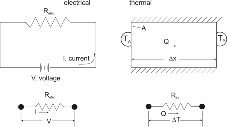
In the thermal analogy with Ohm’s law: ΔT = Q * Rth, where Rth is the thermal resistance, Δx/(k * A). Like electrical resistance, thermal resistance is higher for a longer distance, Δx, and for a smaller cross-sectional area, A.
The concept of thermal resistance is more than an interesting analogy. It’s a useful tool when designing a thermal management system for an electronic device to keep it from getting too hot. The thermal resistance, or the sum of thermal resistances in a more complex structure, is used to quantify the effectiveness of cooling expected from a given thermal management design. To determine the result, it’s generally necessary to measure the temperature.
Measuring temperature – How hot is it?
Temperature is measured by degrees, and degrees go by many names and have several different sizes. Kelvin is the name used in the SI system, while Celsius degrees have the same size as Kelvin and are generally used in engineering. Kelvin starts with zero degrees at absolute zero, the point where there is no molecular or atomic motion, which has yet to be reached in any experiment. Zero degrees Celsius is the freezing point of water, while 100 degrees is water’s boiling point. Two other common types of degrees are Fahrenheit and Rankine. Like Kelvin and Celsius, Fahrenheit and Rankine have the same size. Rankine uses the Fahrenheit scale, adjusted so that 0° Rankine equals absolute zero. When referring to temperatures, the symbol ° is usually used, such as °C, °F, and °R (or °Ra). Unlike the other measures, Kelvin does not use the ° symbol.
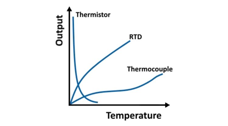
While many thermometers have been developed to measure temperature, they are rarely used in electronics. Thermocouples, thermistors, and resistance temperature detectors (RTDs) are the preferred temperature measurement and thermal protection devices in electronic systems. Thermocouples are widely used and are simple, inexpensive, self-powered devices. Two dissimilar electrical conductors are used to form a thermocouple. The thermal gradient along the wire generates a voltage, the voltage is not generated at the junction, and the voltage can be used to measure the temperature. Thermocouples have limited accuracy, and it’s challenging to design measurement systems with an error of less than one degree Celsius.
There are two types of thermistors: while thermocouples produce a variable voltage, thermistors have a variable resistance based on temperature. The resistance of thermistors can change rapidly at a predetermined temperature threshold.
- Negative temperature coefficient (NTC) thermistors whose resistance decreases as their temperature rises. NTCs are often used as a temperature sensor or as an inrush current limiter.
- Positive temperature coefficient (PTC) thermistors whose resistance increases as their temperature rises. PTCs are often used as resettable fuses and protect against overcurrent conditions or as self-regulating heating elements.
RTDs are fabricated with a thin wire wrapped around a core of glass or ceramic or using thin-film techniques and are made with pure metals such as platinum, nickel, or copper. One of the most common RTDs is the Pt100, fabricated with platinum and has a resistance of 100 Ω at 0 ⁰C. The Pt1000 has a resistance of 1000 Ω at 0⁰C, providing more resolution and increased accuracy for small temperature changes than a Pt100.
Each of these three devices offers designers a different set of performance tradeoffs. (Figure 3). Thermistors typically operate between −100 and 300 °C (but have greater precision when the range is limited to −90 to 130 °C), thermocouples have a wider range of −180 to 2,320 °C. RTDs are rarely used above 660 °C and are suited for precision applications.
Infrared thermometers and thermal imaging
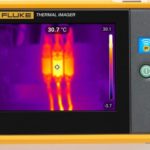
Thermal imaging cameras and non-contact infrared (IR) thermometers are both used for non-contact temperature measurements by detecting IR radiation and translating it into a temperature reading. During product development, they can be used to identify hotspots in a design that need further attention and during manufacturing to identify certain classes of fabrication and assembly defects.
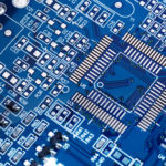
An IR thermometer is highly selective and provides the temperature measurement for a single spot on the target. A thermal imaging camera provides a picture consisting of temperature readings for each pixel in the overall thermal image. Designers can identify a wide range of potential thermal issues during prototype development. For example, in large chips such as field programmable gate arrays (FPGAs), hot spots can develop if the workload is not evenly distributed (Figure 4). A thermal camera can identify these unbalances and help arrive at a more thermally balanced and reliable design.
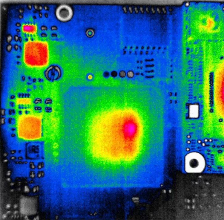
Likewise, using thermal imaging, an operator can quickly identify certain classes of defects such as cold joints simply by comparing the thermal image of a circuit board being tested with a picture of a correctly functioning circuit board.
Arrhenius equation – a practical application of temperature
In general, heat and electronic systems don’t mix well. A common exception is when a new design is undergoing ‘constant temperature accelerated life testing,’ which can also be called ‘elevated temperature accelerated life testing’ based on the Arrhenius equation, which establishes a mathematical relationship between temperature and reaction rates. Using that relationship, electronic devices can be tested at temperatures higher than their normal use temperature to identify design flaws and weaknesses quickly. One limitation of this approach is that it will not identify failure modes related to thermal cycling.
It’s important to identify the optimal temperature for testing. If the temperature is too low, the acceleration factor will also be low. If the temperature is too high, it will result in failures that may not occur during normal operation. When performing an elevated temperature accelerated life test, it’s also wise to analyze the failures to make sure they are representative of the types of failures that would occur during normal operating temperatures. With the correct acceleration factors, testing a product for 1,000 hours at an elevated temperature can be equivalent to operating for over a decade at the normal ambient operating temperature.
Summary
Heat is an important concept when designing electronic systems. All electronics devices generate heat, and effective thermal management is required for reliable operation. Two important elements in designing a thermal management system are the amount of heat to manage and the thermal resistances of the various components and system elements. Various measurement devices such as thermocouples, RTDs, and thermal imaging devices can be useful tools to analyze and monitor the thermal performance of an electronic device. Elevated temperatures can also be an important tool when performing accelerated life testing to identify potential weaknesses in a design.
References
Degree (temperature), Wikipedia
Fundamentals of Thermal Resistance, Celsia
Heat Transfer, Wikipedia
Overview of Temperature Sensors, National Instruments
Printed Circuit Board (PCB) Inspection via Thermal Imaging, Workswell
Quantifying Heat, LibreTexts
What’s the Difference Between IR Thermometers and Thermal Cameras?, Teledyne FLIR


