When the subject is RF design, the word “power” dominates much of the discussion. This FAQ looks at some perspectives related to measurement of this vital RF parameter. Not only is power and measuring it among the most important RF design considerations, it is generally difficult to assess accurately, and it is getting harder to do so. There are two reasons: first, RF frequencies of interest have gone from 500 MHz to 1 GHz, 10 GHz, and now are in the 50-to-100 GHz range for some applications such as 5G; second, there are complex modulation types and formats which add to the difficulty.
As a result, there are many worthwhile application notes, articles, and even books on the subject, two of which are cited in the References. This FAQ will look at some of the basic issues associated with measurement of RF power.
Q: For non-RF circuits, much of the measurement discussion is focused on current and voltage, so why is “power” the primary metric for RF?
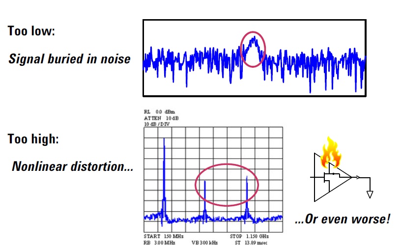
A: There are several reasons. First, power is what really counts in a system. The challenge in an RF design is to endure you have enough of it to “activate” the next stage, whether it is a transmitter driving an antenna, or a low noise amplifier (LNA) stage driving the front end of a receiver. There has to be enough power to exceed the noise, for example, or for a transmitted signal to reach and be “seen” by a receiver despite free-space path loss. If signals are too powerful, the result is distortion and saturation; if too low, they can be buried in noise, Figure 1.
Fig 1: For an RF system to function properly, the signal power must be within a certain range; it must be high enough to overcome noise, yet not so high that that circuits are saturated or overloaded. (Image source: Keysight Technologies)
At lower frequencies, voltage and current are really “stand-in” parameters for assessing power. Second, in the RF world, voltage and current vary with position along the transmission line (and in RF, almost everything is a transmission line) due to the interaction of incident and reflected RF waves, while power is constant along the line. Therefore, a measurement made in the conventional, non-RF way would not be meaningful.
Q: To determine power at lower frequencies and DC, it’s common to simply measure the voltage across a known resistor, then calculate P = IV. Won’t this work at RF?
A: No, as there are too many issues associated with impedance matching, effect of measurement probes, and current and voltage being out of phase. Plus, the presence of the resistor itself affects the RF situation and would largely negate the possibility of obtaining a valid reading.
Q: Power can be measured in many ways; what are the units for RF power?
A: There are several common measurement designations. First, there’s absolute power, such a 1 W or 50 W. There is also dBm, which is power referenced to 1 mW and designated as dBm. This is useful because many RF signals, with the exception of larger transmitters, are at fairly low levels (such as from -20 dBm to +50 dBm). The use of dBm is very convenient as system-channel losses and gains are computed in using the dB scale: these simply add up along the signal chain. This makes it easy to calculate the final output power given the input power and the gains/losses along the way. (If you are not familiar with the use of dB scale, that’s the first thing to learn and learn well!).
Q: What are some of the key RF power-measurement points and aspects of interest?
A: There are many, but there are several which are common across most RF applications. These include:
- output power, whether from a power amplifier feeding an antenna, or from one RF stage to the next;
- power across a wider band of interest, such as the 2.4 GHz Wi-Fi band, which is a rough indication of how much noise and interference from other sources is present;
- narrowband noise, which is overlapping with or adjacent to the frequency of operation;
- received power, which indicates how much of the power from the source – a transmitter/antenna pair or the output of a previous stage – has reached the input of the receiver or the next stage, respectively. Received power at an antenna is usually quite low, such as -100 dBm (roughly in the microvolt range);
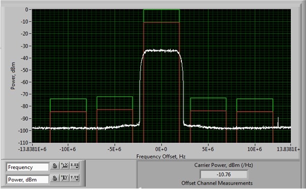
- noise power, both in-band and out-of-band, which tells you how much ambient RF noise is in the band of interest; this is used to get a sense of the needed signal-to-noise ratio (SNR), Figure 2.
Fig 2: Among the many critical RF-power measurements is the determination of RF power in channels adjacent to the one of interest. (Image source: National Instruments)
Q: Is RF power measured at a single frequency, across a band, or across a wide spectrum?
A: All of the above, depending on the application and the situation being investigated. Designers are concerned with their own RF signal at a single frequency, the RF environment in which that signal must function (the band), and the wider spectrum with both random noise and possible interfering signals which may overload sensitive circuits (even if they some distance from the carrier frequency).
Part 2 of this FAQ looks at the different RF signals and shapes which must be measured, and the basic sensors which can be used.
References
- Agilent (now Keysight) Technologies, “Power Measurement Basics”
- Agilent (now Keysight) Technologies, Application Note 64-1B, “Fundamentals of RF and Microwave Power Measurements”
- National Instruments, “5 RF Transmitter Measurements Every Engineer Should Know”
- Boonton/Wireless Telecom Group, “Principles of Power Measurement”






Leave a Reply
You must be logged in to post a comment.