By Anil Pandey
RFID — Radio-Frequency Identification — provides a unique identifier for that object and just as a bar code or magnetic strip the RFID device must be scanned to retrieve the identifying information. An RFID system has three parts:
A scanning antenna
A transceiver with a decoder to interpret the data
A transponder – the RFID tag – that has been programmed with information
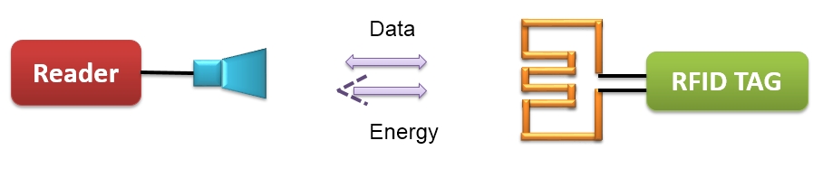
In most of the RFID system, tags are attached to all items that are to be tracked. These tags are made from a tiny tag-chip that is connected to an antenna. The tag chip contains memory which stores the product’s electronic product code (EPC) and other variable information so that it can be read and tracked by RFID readers anywhere. An RFID reader is a network connected device (fixed or mobile) with an antenna that sends power as well as data and commands to the tags. The RFID reader acts as an access point for RFID tagged items so that the tags’ data can be made available to business applications.
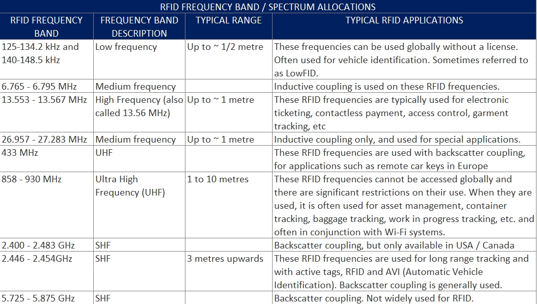
RFID Frequency Band Allocation
There are a number of RFID frequencies, or RFID frequency bands that systems may use. There is a total of four different RFID frequency bands or RFID frequencies that are used around the globe.
RFID Antennas
As part of the design of the RFID antenna, parameters such as the radiation resistance, bandwidth, efficiency, and Q all need to be considered, so that the resulting design for the RFID antenna meets the requirements and allows the required level of performance to be achieved. RFID antennas are tuned to resonate only to a narrow range of carrier frequencies that are centered on the designated RFID system frequency.
The RFID antenna propagates the wave in both vertical and horizontal dimensions. The field coverage of the wave and also its signal strength is partially controlled by the number of degrees that the wave expands as it leaves the antenna. While the higher number of degrees means a bigger wave coverage pattern it also means lower strength of the signal. Passive RFID tags utilize an induced antenna coil voltage for operation. This induced AC voltage is rectified to provide a voltage source for the device. As the DC voltage reaches a certain level, the device starts operating. By providing an energizing RF signal, a reader can communicate with a remotely located device that has no external power source such as a battery. According to the different functions in the RFID system, the RFID antennas can be divided into two classes: the tag antenna and the reader antenna.
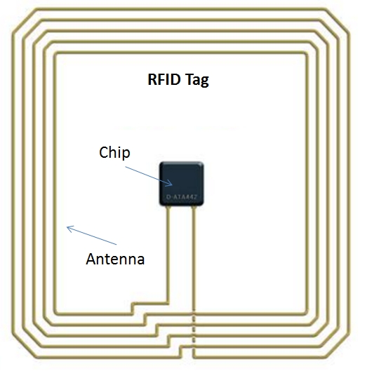
Tag Antenna
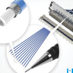
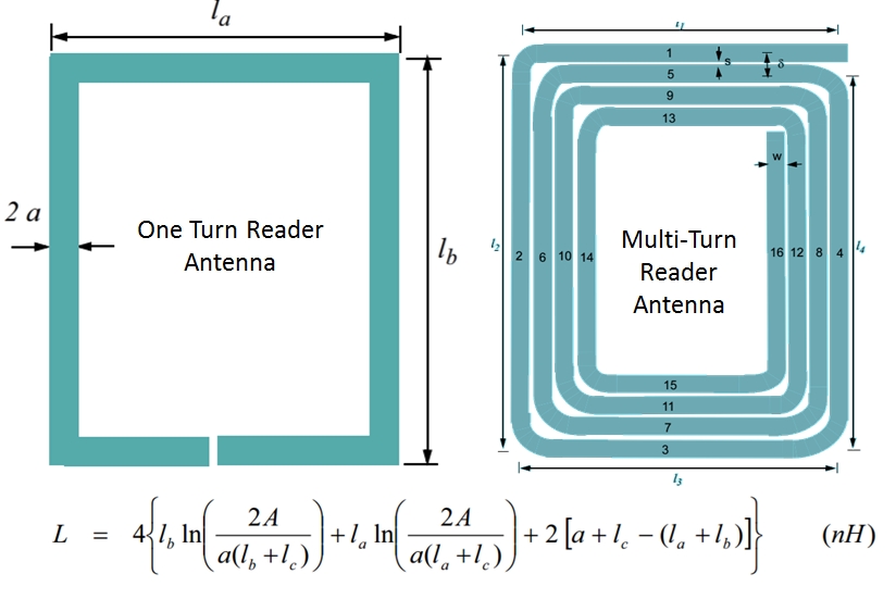
Tag antennas collect energy and channel it to the chip to turn it on. Generally, the larger the tag antenna’s area, the more energy it will be able to collect and channel toward the tag chip, and the further read range the tag will have. Tag antennas can be made from a variety of materials; they can be printed, etched, or stamped with conductive ink, or even vapor deposited onto labels. The tag antenna not only transmits the wave carrying the information stored in the tag, but also needs to catch the wave from the reader to supply energy for the tag operation. Tag antenna should be small in size, low-cost and easy to fabricate for mass production. In most cases, the tag antenna should have omnidirectional radiation or hemispherical coverage. Generally, the impedance of the tag chip is not 50 ohm, and the antenna should realize the conjugate match with the tag chip directly, in order to supply the maximum power to the tag chip. Tag antenna may be a signal turn or multiple turns as shown here.
Reader Antenna
Reader antennas convert electrical current into electromagnetic waves that are then radiated into space where they can be received by a tag antenna and converted back to electrical current.
RFID Antenna Design
This design RFID system is used to track object placed on a storage rack. In this system, there is two component of RFID.
RFID Reader: this component is fit on the shelf and connected to data base computer system
RFID Tag: this component along with planar antenna is placed in tracking objects placed in store
When a particular object placed on the shelf or removed from the shelf, information of that object is automatically updated in database computer. The antenna is optimized to increasing the read accuracy and shortening the optimization phase. One more RFID transponder antenna designed at 13.5 MHz is shown below.
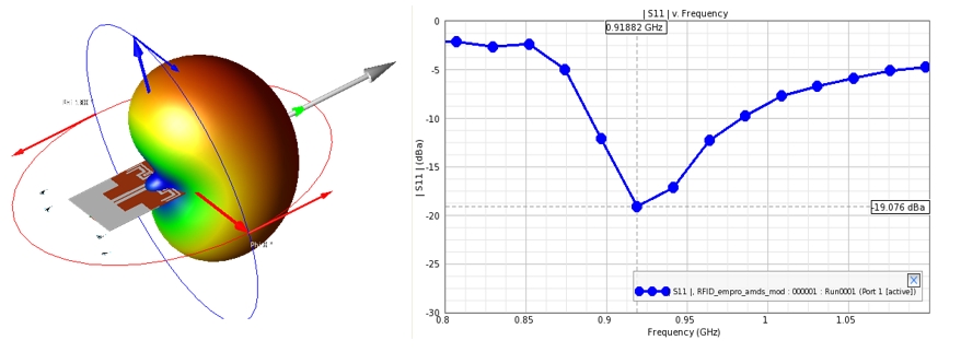
Planar Antenna for Ultra High Frequency (UHF) RFID Handheld Reader
This antenna consists of a microstrip-to-coplanar stripline transition, a meandered driven dipole, a closely-coupled parasitic element, and a folded finite-size ground plane. This Antenna is suitable for RFID handheld readers.
The post How do RFID tags and reader antennas work? appeared first on Analog IC Tips.