Across a wide range of applications, it is necessary to need to accurately sense the motion of a rotary shaft and know its position, speed, or even acceleration. To do this, a component called a shaft or rotary encoder is added to the motor/shaft assembly. (Note that the term “rotary encoder” is often shortened to simply “encoder,” but it is important not to get this “encoder” confused with the many other types of electromechanical and electronic encoder functions in use, such as those which encode data from one format to another.)
Although it is possible to use a brush to touch a conductive part on a shaft and so complete a circuit – analogous to a DC motor commutator – the resolution and long-term reliability of this approach is inadequate. Instead, a non-contact encoder is used.
Q: How are encoders implemented?
A: The two most-common approaches to implementing the rotary encoder use optical and magnetic techniques. Each approach has characteristics which make it a good fit (or not so good) in some situations. Both are “digital” in the sense that they generate pulses corresponding to the rotary motion, rather than an analog signal which is in some way related to the shaft angle.
Q: What are the functional elements of the optical encoder?
A: The optical encoder has an LED light source, a light detector, a “code” disc/wheel mounted on the shaft, and output signal processor, Figure 1. The disc has alternating opaque and transparent segments and is placed between the LED and detector so it intermittently interrupts the LED’s beam as it rotates. The detector responds to the series of light pulses it receives and sends that information to the processor, which actually extracts the motion information (both amount of rotation and direction).
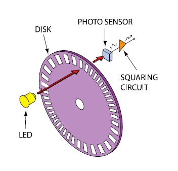
Fig 1: The principle of the optical encoder is simple: generate an electrical pulse each time light passes through one of the many slots in a rotating code wheel. (Image Source: Encoder Products Company)
Q: How is shaft direction determined?
A: The encoder uses the “quadrature” principle where the single light beam is split into two parallel beams called A and B. The beams are aligned so their outputs differ by 90° as they pass through the encoding disk, and they are detected separately. The relative phase between the A and B outputs indicated which direction the encoder, and thus the shaft, is rotating, Figure 2. These two output signals determine the direction of rotation by detecting the leading or lagging signal in their phase relationship.
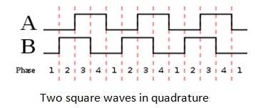
Fig 2: By using quadrature signals (two signals 90° out of phase) – and looking at their relative lead/lag difference as they appear, the direction of rotation can be quickly and easily determined. (Image source: Anaheim Automation)
Q: What are the roles of the signal processor?
A: The two roles of the signal processor are to amplify and “square up” the quadrature outputs from the A and B photodetectors to produce digital output pules, and to also indicate their relative phase by controlling a direction output signal as well. Using these two signals – one for the rotation pulses on the code wheel, and one for the direction determined by the quadrature phase – the system can determine both rotation speed and direction.
Q: What are the two most commonly used basic encoder classes?
A: Encoders comer in two broad classes: incremental (relative) and absolute. In the incremental encoder, the output of the encoder indicates only changes from one position to another; in the absolute encoder, the output indicates the actual shaft angle with respect to a “zero-degree” point. Some applications need absolute indication, but there are many where incremental indication is all that is required.
Q: What about the power-up situation?
A: An absolute encoder can indicate the shaft angle once power s applied. An incremental encoder can only report it after the “zeroing” operation is applied after power up. You have likely seen and heard this sequence in action when powering up a device such as an inkjet printer: on power-up, the carriage slides all the way to one end to establish a zero reading and then uses incremental readings from that point forward.
Q: What is the resolution achievable via the code wheel?
A: The code wheel determines the resolution of the encoder. In theory, the light/dark slots can be made thinner and spaced more tightly to increase the resolution, but light feeds through adjacent slots (crosstalk) and causes sensing errors. In practice, resolutions of 12 bits – one part on 4096 – are practical. Some very high-end, larger-diameter optical encoders can reach five times that resolution.
Q: Why are some other code wheel issues?
A: The code wheel can be made of glass for “cleanest” lines and highest stability, but glass is fragile and costly, Figure 3. Some encoders use much lower-cost Mylar instead, but this material may not be able to hold the lines as well. Others use chemically etched metal, which is between Mylar and glass in cost but more rugged. Each code-wheel material has performance and cost tradeoffs.
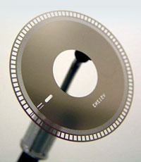
Fig 3: The code wheel is at the heart of the optical encoder; glass versions, such as this one, have some advantages in resolution and stability but also has downsides in cost and ruggedness. (Image source: Thin Metal Parts)
The code wheel’s mechanical parameters are critical to encoder performance., Not only must it be dimensionally stable, but its inner diameter opening (which accepts the rotor shaft) and the outer diameter (which is where the lines are sensed) must be perfectly aligned and concentric. If they are not, the code wheel will not be balanced and thus will vibrate at higher rotational speeds, leading to early encoder failure. Also, the code wheel must fit without “slop” on that shaft, for the same reasons.
Q: What are some other issues with the optical encoder?
A: In general, optical encoders are reliable (if used appropriately) but suffer some potential weaknesses. First, there is the well-known dimming of LEDs over time. Second, they are not sealed so dirt, grit, oil, and other contaminates can get between the layers of the LED/code wheel/photodetector assembly and affect reliability. Third, they are not suitable for high-temperature operation, due to the LED and photodetector. Finally, the code wheel itself is an issue if it changes dimensions with temperature.
Q: Can an optical encoder be used for absolute position information?
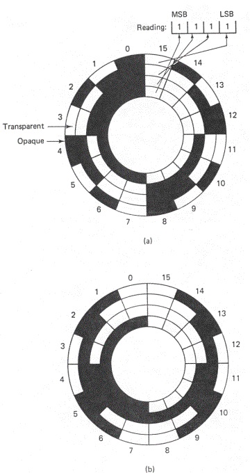
Fig 4: Using conventional binary coding, more than one bit can change between adjacent counts (upper disk), while in Gray-scale encoding, only one bit can change from one count to the next lower or higher. (Image Source: K. Craig, NYU Engineering)
A: Yes, but it is complicated. Instead of a simple series of slots of the code wheel, the wheel has a set of binary patterns, usually using Gray code (a code where adjacent positions differ by only one bit), Figure 4, which avoids ambiguities in bit switching. Multiple sensors are then used to simultaneously read the pattern in a line radiating from the shaft outward.
Another approach is to use a separate track (called the Z track) on the code wheel, which has one slot used only for indexing. This is sensed separately and used to generate a single pulse each time the index slot passes a separate photodetector. To use this scheme, the system must combine the knowledge of the index pulse and the incremental pulses. Note that with an absolute encoder, system design can be simplified because there is no need to perform a reference cycle or return to home function to determine the true machine position.
Q: What is the cost of an optical encoder? What power does it need?
A: Prices vary by resolution and ruggedness, but an approximate range is $1 to $5 each, including the fully conditioned quadrature outputs. Most optical encoders need a single DC supply, typically 5 V at about 50 mA.
Part 2 of the FAQ will look at the magnetic encoder, an alternative to the optical encoder.


Good summary, will look for mag encoder article.