• Skip to primary navigation
  • Skip to main content
  • Skip to primary sidebar
  • Skip to footer

Electrical Engineering News and Products

Electronics Engineering Resources, Articles, Forums, Tear Down Videos and Technical Electronics How-To's

  • Products / Components
    • Analog ICs
    • Connectors
    • Microcontrollers
    • Power Electronics
    • Sensors
    • Test and Measurement
    • Wire / Cable
  • Applications
    • Automotive
    • Industrial
    • IoT
    • Medical
    • Telecommunications
    • Wearables
    • Wireless
  • Resources
    • Covid-19
    • DesignFast
    • Ebooks / Tech Tips
    • EE Forums
      • EDABoard.com
      • Electro-Tech-Online.com
    • FAQs
    • 2020 LEAP Awards
    • Oscilloscope Product Finder
    • Podcasts
    • Webinars / Digital Events
    • White Papers
  • Videos
    • Teardown Videos
  • Lee’s Teardowns
    • Teardown Videos
  • Learning Center
  • 5G
  • Women in Engineering

Trigger-and-decode scope setup handles 1000BASE-T1 automotive Ethernet

February 8, 2021 By Lee Teschler

The new K58 option for R&S RTO and R&S RTP scopes is billed as the world’s first triggering and decoding solution for 1000BASE-T1.

The flexibility of Automotive Ethernet makes the simple twisted-pair network technology R&S scopesa candidate for an ever-increasing range of in-vehicle networks. To verify, commission and troubleshoot designs based on an Automotive Ethernet communication link, it is important to have an instrument that is capable of not only measuring and verifying compliance to the standards but also decoding the messages and reliably triggering on them.
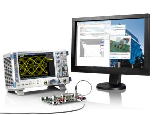
The new K58 option for the R&S RTO and R&S RTP oscilloscopes provides a fast and efficient means to perform this analysis. Users can debug and verify their in-vehicle networks and ECU implementations. The decoded data can be displayed in a table as well as in the usual honeycomb diagram. Important parameters such as Idle, MAC or error frames are easily identifiable via defined color codes. With the R&S RT-ZF7 probing fixtures, both the forward and reverse data streams can be decoded simultaneously. Additionally, the oscilloscopes support simultaneous decoding of up to four serial buses.

Comprehensive search functions simplify analysis of long signal sequences. Specific message types, content and errors can be quickly isolated. All detected events are shown in a table with timestamps. The user can then examine the individual events in a zoom window with the proper timing correlation and navigate between the events.

Combining the new trigger & decode functionality with the unique K35 bus measurements option, in-depth measurements like the error frame rate and number of consecutive frame errors, helps to determine quickly the stability of the link. More analysis of bus timing, such as the delay between frames or between any trigger event and the subsequent bus frame can be discovered. The error rates as well as frame timing are measured simultaneously, both very important for automotive applications such as for autonomous driving.

Rohde & Schwarz oscilloscopes decode protocol-specific trigger results, allowing fast and reliable debugging. The unique capability of combining bus measurements and statistics offers great insight into bus capacity, error frame rates and latency issues. This enables faster development processes and gives engineers confidence in reliable performance of their products. No additional instruments are required.

You may also like:


  • Compliance tests cover 2.5/5/10GBASE-T1 automotive Ethernet speeds

  • 100BaseT1 automotive Ethernet protocol analyzer handles next-generation network debugging

  • Test setup measures automotive Ethernet latency with nanosecond precision

Filed Under: Applications, Automotive, Test and Measurement Tips Tagged With: rohdeschwarz

Primary Sidebar

EE Training Center Classrooms

“ee

“ee

“ee

“ee

“ee

Featured Resources

  • NEW! EE World Online Learning Center
  • CUI Devices – CUI Insights Blog
  • EE Classroom: Power Delivery
  • EE Classroom: Building Automation
  • EE Classroom: Aerospace & Defense
  • EE Classroom: Grid Infrastructure

February 2021 Special Edition: Power Electronics Handbook

RSS Current EDABoard.com discussions

  • Help with simple op amp circuit
  • Which of these common mode chokes has the highest attenuation?
  • Driving a pmos using MCU
  • Help to create a Gerbe file in RS-274X format
  • High side Alternatives for ULN2003

RSS Current Electro-Tech-Online.com Discussions

  • First time soldering
  • Cycle Indicator Lights
  • New to 3D print, not so new in stepper motors
  • Diode that only allows continuity at 13.5v?
  • Can two N-Channel MOSFETs be connected in series to perform a "AND" function?

Oscilloscopes Product Finder

Follow EE World on Twitter

Tweets by @EEWorldOnline

Footer

EE World Online

EE WORLD ONLINE NETWORK

  • DesignFast
  • EDABoard Forums
  • Electro-Tech-Online Forums
  • Microcontroller Tips
  • Analog IC Tips
  • Connector Tips
  • Engineer's Garage
  • Power Electronic Tips
  • Sensor Tips
  • Test and Measurement Tips
  • Wire & Cable Tips
  • 5G Technology World

EE WORLD ONLINE

  • Subscribe to our newsletter
  • Lee's teardown videos
  • Advertise with us
  • Contact us
  • About Us
Follow us on TwitterAdd us on FacebookFollow us on YouTube Add us on Instagram

Copyright © 2021 · WTWH Media LLC and its licensors. All rights reserved.
The material on this site may not be reproduced, distributed, transmitted, cached or otherwise used, except with the prior written permission of WTWH Media.

Privacy Policy