Radiated emissions standards are generally more focused on higher-frequency noise sources. At about 30MHz, there is a transition between concern with conducted and radiated emissions. Above that frequency, conducted emissions are not usually a major problem. And below 30MHz, the various interconnects and conductors in most electronic systems are not effective antennas for emitting radiated EMI. From about 30MHz and above, those same interconnects and conductors can become antennas with the ability to radiate RF energy and potentially generate harmful EMI.
The table below provides an overview of several areas covered by specific radiated emissions standards. In addition to these commercial, industrial, and consumer standards, there are a variety of military and aerospace standards for emissions. As discussed in the previous FAQ is this series, among the most commonly-specified are the MIL-STD-461 test procedures that define the test levels and test limits of electronic equipment used by the US military. In addition, the Society of Automotive Engineers (SAE) has a wide range of EMC-related standards. Those SAE standards include conducted and coupled EMI but also have a strong emphasis on radiated emissions and compatibility testing. With the growing electronics content in automobiles and the emergence of autonomous vehicles, related EMC concerns will continue to grow in importance.
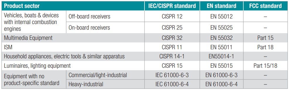
Summary of main product standards for radiated emissions (Image: Texas Instruments)
Bypass capacitors and grounding
The use of bypass capacitors and effective grounding schemes are important aspects of radiated EMI control. For example, in the case of high-speed digital ICs, the bypass capacitors need to be as close as possible to the pins that are the source of the noise. That includes not only the power supply pins, but extends to highly-active address and data lines in microcontrollers and memory ICs. Proper use of decoupling capacitors and well-designed grounding schemes will minimize the formation of loop antennas on the circuit board traces. Multiple ground planes are often needed in a circuit board to maintain low radiated emissions. Some design considerations to maximize the effectiveness of ground planes include:
- Ground planes should be as large as possible
- Multiple ground planes can improve performance, this may require additional circuit board layers
- Ground planes should extend directly under high-speed signal traces
- The physical integrity of ground planes should be maintained and the number and sizes of vias or other cutouts should be minimized
Shielding and radiated EMI
In addition to minimizing the sources of radiated emissions using bypass capacitors and effective grounding and minimizing common-mode conducted energy (see the discussion of differential- and common-mode EMI in the previous FAQ in this series, “Conducted and Coupled EMI/EMC Concepts”), shielding can be an effective tool for controlling radiated emissions, minimizing electromagnetic susceptibility and maintaining electromagnetic compatibility. EMI shielding comes in many shapes and sizes for a multitude of specific application needs.
Faraday shields, or cages, made of various metals are commonly used to shield transmitter and receiver sections of devices. The level of attenuation provided depends on a variety of factors including the material used and its thickness, the size of the Faraday cage and the size, shape and orientation of any open apertures.
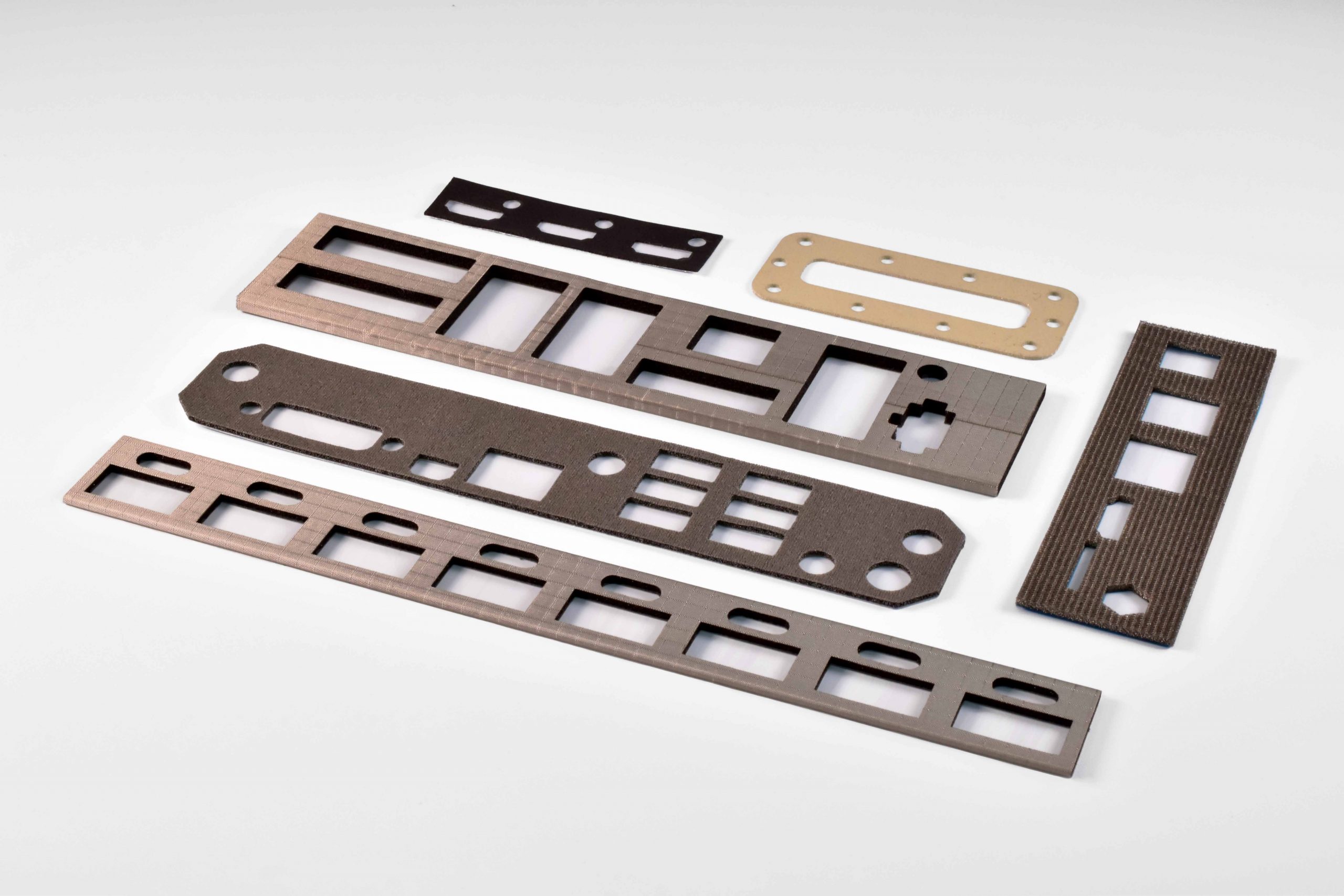
Selection of EMI Shielding Gaskets (Image: Leader Tech)
Conductive elastomer gaskets can provide effective EMI shielding and environmental protection for enclosures. These gaskets can be found in a wide variety of products from consumer devices to medical and military systems. High-performance conductive elastomer gaskets can provide up to 110dB of shielding and at the same time provide environmental protection. EMI vent panels for ventilation and cooling applications combine conductive gaskets with honeycombs of aluminum mesh to provide effective shielding while still allowing the required airflow.
Testing for radiated EMI
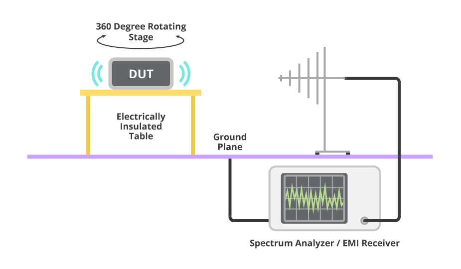
Basic radiated emissions testing setup (Image: CUI, Inc.)
As is the case for conducted emissions, good design practices are required to control radiated EMI, and testing is also essential. Early testing can accelerate the certification process that is required before taking products to market. In-house testing does not generally replace certification by an independent testing laboratory. But in-house testing during product development can provide early identification of potential trouble areas and shorten time to market.
Testing radiated emissions requires a spectrum analyzer and a suitable antenna. While conducted emissions testing can be performed in a relatively small working area, testing radiated emissions requires a larger test environment. Radiated emissions testing needs to be performed in an electrically quiet environment (preferably a shielded room or absorber-lined shielded enclosure (ALSE)) large enough to have the antenna at least 3 meters from the device being tested.
The antenna is an important element in successful radiated emissions testing and needs to match the requirements outlined in the individual standard being considered. For example, CISPR 25 recommends specific antenna designs for various frequency ranges (note there are instances of overlap):
- 150kHz to 30MHz – 1m vertical monopole with counterpoise (vertical polarization only)
- 30MHz to 300MHz – biconical (vertical and horizontal polarization)
- 200MHz to 1GHz – log-periodic (vertical and horizontal polarization)
- 30MHz to 1GHz – broadband (vertical and horizontal polarization)
- 1GHz to 2.5GHz – horn or log-periodic (vertical and horizontal polarization)
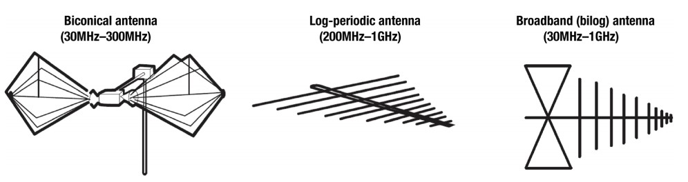
Measurement antennas referenced in the CISPR 25 specification (Image: Texas Instruments)
References:
An overview of radiated EMI specifications for power supplies, Texas Instruments
Electromagnetic Shielding, Wikipedia
EMI Gaskets, Leader Tech
The Importance of EMC Testing Early in Your Product’s Design, CUI, Inc.