Spring-loaded connectors are available in multiple high-quality precision-machined solutions to give designers extensive choice.
Stephen Capitelli, Manager of Product Engineering, Mill-Max Mfg. Corp.

The spring is the critical component in an SLC
Connectivity is crucial in modern design. The availability of highly reliable and proven connector technologies that facilitate miniaturization and connectivity make a significant contribution to the growth of modern portable devices and other applications. Designers must achieve the right balance between reliability, suitability and cost for the connectors they specify. Therefore, the application and connectivity requirements need to be clearly understood.
In some applications, the connector is mated only once; in others—such as docking stations or chargers—the connector is integral, meaning that each of these applications requires a different solution. In all cases, a correctly applied connector functiDons better and lasts longer.
There are several methods for creating connector pins although the most dependable is precision machining as it provides excellent quality and reliability. The process is highly accurate with exceptional repeatability. It also offers significant design and material flexibility, allowing designers to specify connectors to suit their exact needs. Typical high-precision pins have a basically cylindrical geometry and are sometimes called ‘turned’ pins.
Typical turned pin sizes range from 0.008 to 0.250 in. (0.2032 to 6.35 mm) with tight tolerances of ±0.0005 in. (0.0127 mm) on all features that are critical to using the pin as a connector.
Specifying spring-loaded connectors
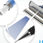
The main component in spring-loaded connectors (SLCs) are the spring-loaded pins (sometimes called spring-loaded contacts, spring probes, or Pogo Pins) that provide a highly reliable, interconnect solution for many demanding applications. Each pin is precision-machined to ensure a high quality, low resistance and compliant connector, thereby giving it an edge over other technologies.
Spring-Loaded pins typically comprise at least three machined components assembled with a spring allowing a range of movement. Each component is electroplated with gold over nickel ensuring excellent electrical conductivity, durability and corrosion protection for life.
Many options requiring should be considered when specifying SLCs, including the basic requirements of voltage capability, current handling and contact resistance.
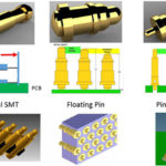
While vertical mounting is most common, certain applications require the horizontal mating of two (or more) boards. Right-angle pins and targets (both through-hole and surface-mount) on a 0.100 in. (2.54 mm) or 0.050 in. (1.27mm) pitch solve this challenge.
SLCs often carry both power and signals within the same assembly. Standard power pins carry currents up to 9 A with only a 10°C rise above ambient. Where higher current (or lower temperature rise) is required, pins may be doubled up, or larger pins used, especially for ground connections.
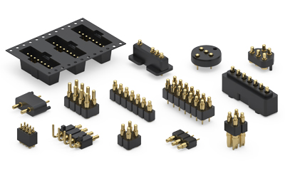
Spring-Loaded pins are available in many shapes and sizes to suit a wide variety of applications.
Specifying different length spring pins in an array allows ‘make-before-break’ connections. This is especially useful where power needs to be applied to a circuit before signal connections, or key signals need to mate sooner or later, based on the application requirements.
Depending upon the application, different travel distances or spring forces may be required. For complex, multi-board assemblies, double action SLCs are available.
SLC technology is inherently versatile; pins with solder cups or crimp barrels are suitable for wire termination. Various sizes are available offering the ability to accommodate wires up to 16 AWG, with 9 A current handling capability.
Generally speaking, it is best to operate SLCs around mid-stroke, with 25-75% compression, although ‘one-time compression’ applications often benefit from maximum compression. For very low profile spring pins, 50 to 85% compression is preferred. Good design practice in less-controlled applications includes incorporating a stand-off to provide mechanical support.
SLCs are able to mate with many different surfaces as a good connection is made when the plunger/piston contacts any flat or concave plated surface. Spring pins can mate with non-parallel surfaces, provided the mating force is applied axially to the piston/plunger. Lateral engagement or side-loading may cause damage.
By using spring-loaded connectors and mating with PCB pads, one side of the ‘pin and socket’ combination is eliminated, leading to savings in component cost and production time. Although mating with gold-plated PCB pads is most common, other options are available. A dedicated through-hole nail head pin, surface mount target pin, low-profile, gold-plated discs or a variety of target connectors can be used. All provide a highly conductive, wear resistant solution. Combining spring pins with targets allows different mating distances to suit any application.
Reliability is required
Poor quality connections negatively impact overall system reliability, making reliability crucial to specifying SLCs. As such, when specifying SLCs, designers should review all available test data.
IEC 60512 has been the definitive standard for connector testing since 1976. It includes multiple tests to ensure that the connectors will give long-term reliability in real-world applications. Spring force, contact resistance, random, half sinus and sinusoidal vibration, rapid temperature change, dry heat, cyclic damp heat, cold test and current carrying capacity are examples of included tests.
Applications of SLCs
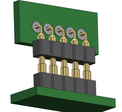
Typical right-angle board-to-board SLC solution
SLC applications are only limited by the specifying designer’s imagination, although the most popular remains connectivity between two or more PCBs.
As modular designs become more popular, the number of PCBs in products is increasing. Versatile SLCs are a viable solution for parallel or perpendicular, vertical or horizontal boards and allow multiple boards to be combined easily, accommodating tolerance stack-ups due to non-parallel fixing or PCB warpage.
Board stacking combined with limited design space is making ‘blind mating’ more common. However, engagement misalignment may lead to damage and poor connections with common socket and header combinations. SLCs are ideal here as no insertion is required; connection is made when the plunger contacts a conductive surface. Mating surfaces are usually larger than the spring pin, eliminating alignment concerns.
While SLC’s simplify the manufacturing assembly process on the inside of the product they are also beneficial when designed as the interface to the outside world. In the example of handheld devices, utilizing spring-loaded pins in the battery compartment of the device eases the installation and removal of batteries, while positioning them in docking stations facilitates charging and signal functions. Easily integrated into any system with numerous options for height, travel and spring force, SLCs provide a durable, consistent connection, allow blind mating and permit some misalignment when placing the battery or device in the cradle. This makes them the preferred choice for applications where the end user makes the connection.
Spring-loaded contacts with solder cups or wire crimp terminations can be used in harness applications by having them over-molded or press-fit into a plastic housing, thereby creating a cable terminated connector. This is excellent for blind mating and quick connect cable applications, especially as SLC performance under shock and vibration makes them a good fit for the constant handling and jostling of cables.
However, SLCs are not only used in end products. Many test departments rely on them for ‘bed of nails’ automated functional testers where they provide an easily accessible yet high tolerance and reliable means of quickly mounting and de-mounting the board to be tested.
Technology examples
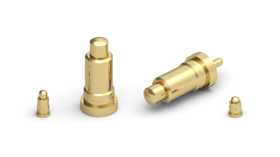
The larger 08xx series of power spring pins shown alongside standard 09xx series contacts
Mill-Max Mfg. Corp. is at the forefront of standard and custom spring loaded connector solutions with a comprehensive range of standard spring loaded contacts and connectors that comprises more than 70 different product families covering almost every conceivable configuration, alongside 45 different target connectors (and 28 loose pin target products).
The range includes single and double row headers suitable for through-hole, surface mount and wire termination that are available on 0.100 and 0.050 in. and 2 mm grids with various force, stroke and height options. In addition, bulk and tape-and-reel packaging is offered to suit a wide variety of production processes.
For rugged applications Mill-Max currently offers nine spring loaded pins designed to withstand side loading, blind mating, over compression, high shock and vibration and other general rough handling by end users. These pins in the 0850 series feature 20 micro-inches of gold plating over nickel giving durable performance up to one million cycles and have extended bearing surfaces and ample body wall thickness as well as solid plungers and stainless steel springs.
The high force spring provides double the force of standard spring pins at working travel and allows for strokes up to 0.090 in. (2.286 mm), allowing the SLCs to excel in rugged environments, operating from –55° to 125°C. The low contact resistance of 20 mΩ (maximum) allows for currents up to 9 A to be handled, with temperature rises below 10°C.
Summary
In modern applications, space is at a premium and reliability is critical. Precision-machined SLCs bring a unique combination of quality, reliability and versatility to a wide range of applications, thereby solving many of the connectivity-related challenges faced by designers.

Leave a Reply
You must be logged in to post a comment.