Over the next few years, autonomous vehicles and advanced driver assistance technologies will significantly increase passenger safety, and finally start fulfilling the long-term promise to transform the economics of ground transportation and logistics.
The self-driving car requires many sensors on the vehicle that enable the complex software stack to do its job of replicating the human control function safely.
At the same time that these sensors accurately perceive and understand the vehicle’s surroundings in real time, they must also simultaneously localize the position and direction (also referred to as heading) of the vehicle with far greater precision and reliability than traditional car navigation systems (like GPS), can obtain.
Consider for a moment a truck travelling down an interstate freeway at 80 mph. Staying safely centered in its lane requires lateral positional control on the order of 30 centimeters. The truck is also traveling more than 3,600 centimeters every second. An error as small as 0.2 degrees in heading or direction will result in the vehicle drifting left or right by those 30 centimeters in just seconds.
To continuously maintain these tight tolerances, the navigation function in automated vehicle control systems relies on a wide range of sensors and data sources.
These sources include the vehicle’s vision sensors (such as lidar and cameras), lower resolution-ranging sensors (like radar and ultrasound), and classic navigation techniques (like GPS and maps). However each of these sensors depend on the external environment, and hence, can experience data-loss or degradation with little warning. For example, in snowy conditions a lidar’s effective range and resolution is reduced. In downtown, urban areas, GPS can suffer from severe multi-path errors and frequent outage.
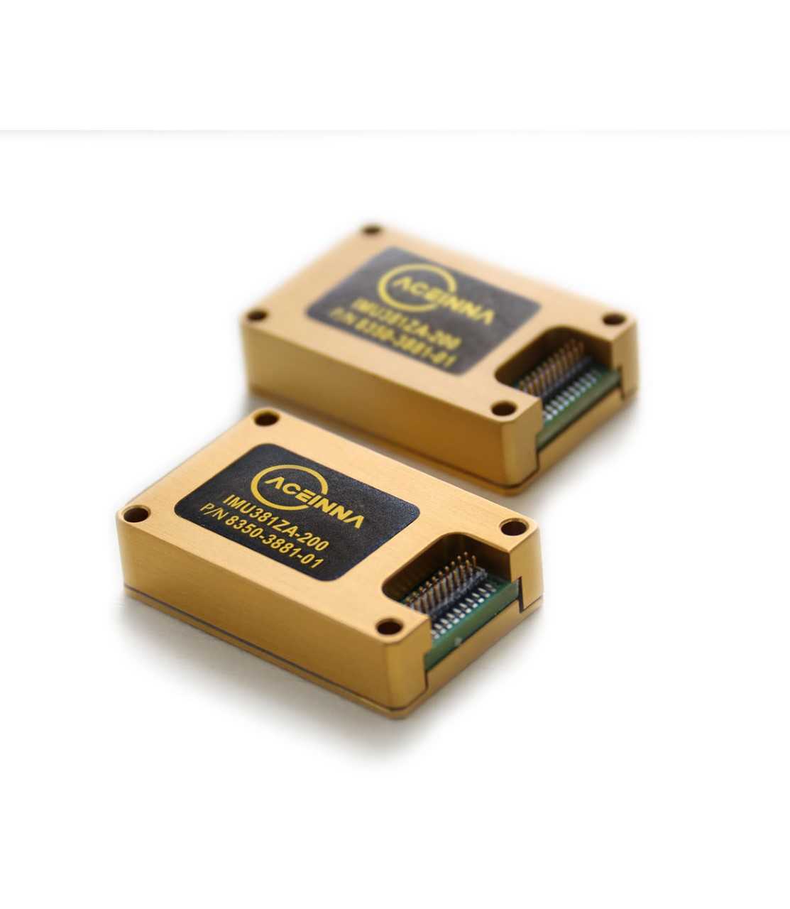
The function of one or more inertial measurement unit sensors (IMUs) on the vehicle is to provide a source of accurate short-term position and heading information to mitigate these environmental challenges ensuring safe control of the vehicle at all times.

IMUs consist of three orthogonally-mounted accelerometers and three orthogonally-mounted rate sensors (gyros) that can directly measure the vehicles’ motion with no external dependencies. The output of the IMU is used to independently navigate or “dead-reckon” for short periods of time. Dead-reckoning, also called free-integration, refers to processing the IMU outputs using Newtonian equations of motion to estimate attitude, heading, velocity, and position of the vehicle.
Dead-reckoning places tremendous challenges on IMU accuracy and requires careful design choices related to both algorithm design and sensor selection. Traditionally, systems capable of dead-reckoning have been called Inertial Navigation Systems (INS), and also go by names of Inertial Reference System (IRS), GPS/INS, or Enhanced GPS/INS (EGI).
Today, these systems are commonly found in aerospace and defense applications. Not only are these systems typically $10,000 or more per unit, but they generally work exclusively with GPS for navigation as opposed to the broader set of sensors in today’s autonomous vehicle and ADAS architectures. Hence, many designs require direct use of IMU data in a sensor fusion algorithm that blends lidar, camera, and radar as well as GPS data into a navigation state estimate.
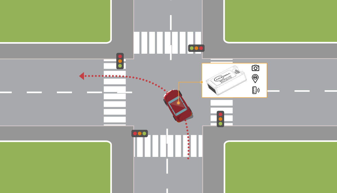
An Automated Left-Turn
One common use case for the IMU is to help reliably navigate intersections. Street intersections with their frequent lack of lane markers and wide-open space can challenge vision systems. Furthermore, in urban environments, there may not be good GPS data available, yet crossing or turning through an intersection safely is fundamental to automated driving. Using this practical use case as motivation, the remainder of this article summarizes error modeling, simulation, and empirical testing techniques to validate IMU accuracy and performance for this application.

Conceptually, dead-reckoning is a fairly simple algorithm. It computes the vehicle’s position directly from IMU data and is like a short-term GPS signal without a GPS radio.
Dead-reckoning works by taking the three-axis rate output and integrating it to orientation. Orientation is simply the vehicle’s combination of heading and attitude (roll, pitch, and yaw). The orientation is used to rotate the measured body frame accelerations into the Earth frame, and then gravity is removed. The resulting Earth frame accelerations are double integrated to position following Newton’s laws of motion. This is diagramed in Figure 3:

A Dose of Reality
Tracking position and velocity with absolutely no external reference is miraculous and super useful. But there is a catch—position drift.
Errors in rate or acceleration can quickly grow due to the integration process. A simple static acceleration error, known as an acceleration bias, will integrate to a linear velocity error, and a quadratic position error. Bias is just one of many types of sensor error, and the analysis quickly gets considerably more complex with gyro rotation errors coupling to position errors as well.
The first step to a real-world assessment of performance is to characterize the error model of the IMU. The error model of IMU typical consists of the errors in the table below.

These errors always need to be considered, however, additional errors can also be important such as the sensitivity of the gyro to linear acceleration, and the accelerometer bias sensitivity to vibration. Determining the exact values of these parameters for a MEMS sensor can be complex and require the development of a special characterization Kalman filter, or sophisticated test equipment such as rate tables, ovens, and shaker systems. While some simple approximations can provide guidance such as those outlined in Figure 3, the relationship of these sensor errors to the position and velocity errors given an arbitrary motion profile is quite difficult to model analytically. Hence, simulation is generally the best method to really get a handle on performance prior to drive testing.
Simulation of an IMU
GNSS-INS-SIM makes it simple to combine an IMU error model and a realistic motion trajectory into an accurate simulation of dead-reckoning performance. GNSS-INS-SIM is also a useful tool to evaluation sensor fusion algorithms such as Kalman filters, particle filters, and other navigation algorithms. GNSS-INS-SIM has error models already defined for many popular IMU’s including Aceinna’s own line up of IMU’s.
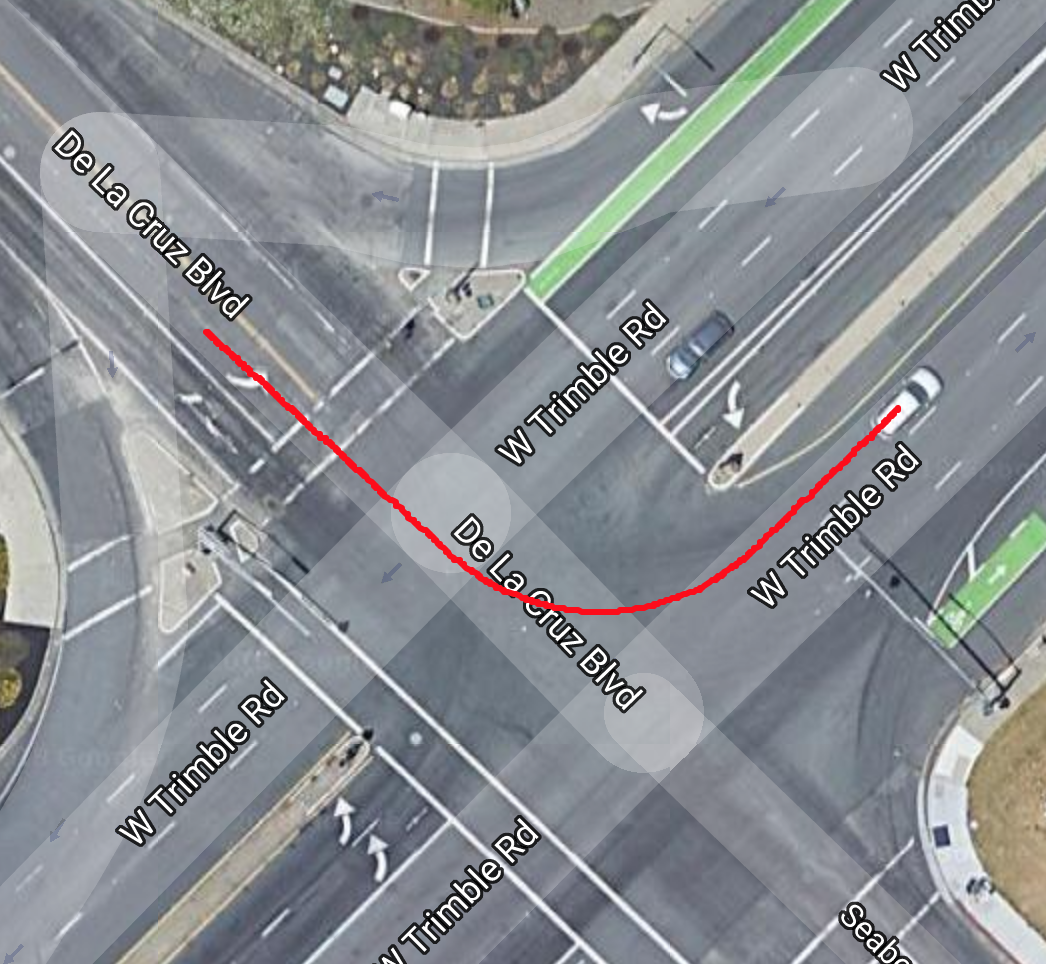
The motion trajectory to be simulated is specified by a CSV file, called a motion definition file. GNSS-INS-SIM provides an out-of-box implementation of dead-reckoning. Once an error model is selected and a motion profile specified, a Monte-Carlo style simulation is run quickly and results generated. GNSS-INS-SIM generates a Google Maps compatible KML output so the position output can be graphically seen on top of a map. This is particularly useful when comparing simulation to drive test results.
The example results shown in Figure 4 are for an error model of the Aceinna OpenIMU300ZA and the motion trajectory of a left-hand turn at an intersection in San Jose, California.

Drive Testing an IMU
The last step to validate an IMU’s performance is to perform real-world dynamic accuracy testing. To facilitate this, an accurate aerospace-grade inertial reference system must be used. One system frequently used for research and development testing is the Novatel SPAN product line. The Novatel SPAN utilizes Novatel’s multi-frequency GPS card and supports RTK corrections to achieve dynamic position accuracy of <2 cm in clear sky conditions.
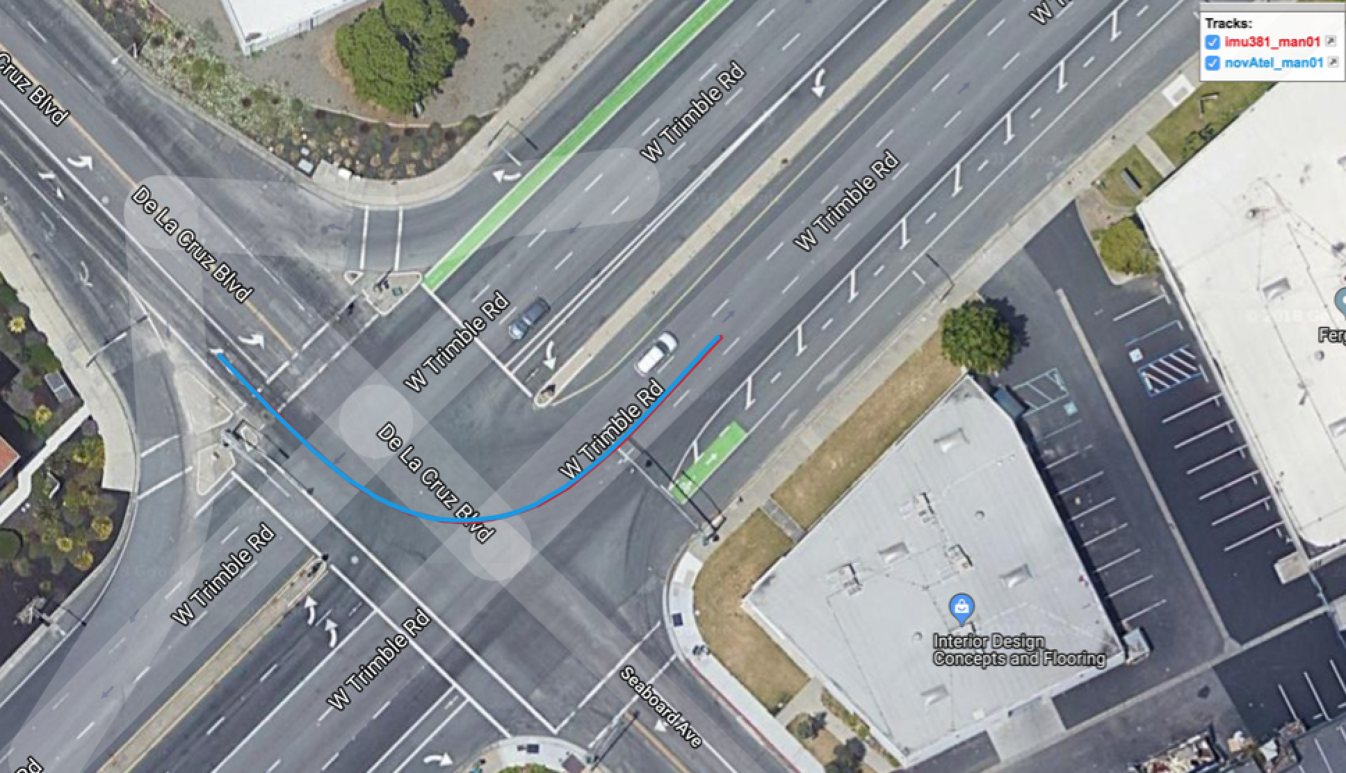
To validate that our error model and our simulation is correct, a car is outfitted with a Novatel SPAN system, as well as an IMU381ZA is driven. Data is collected from the location that was used in the simulation, and care is taken to drive the turn in a repeated fashion and as consistently with the motion profile in the simulation as possible.
The IMU381ZA data is processed thru the dead-reckoning equations of motions without any corrections. The results are shown in Figure 5. Actual performance is similar to the simulation, confirming the validity of the error model and simulation methodology.

Conclusion
The design and development of navigation systems is a complex process. However with vehicle and robotic automation applications on the rise, sophisticated and accurate navigation requirements are becoming even more complex.
Knowing the basic theory of an IMU measurement and using tools such as simulation can facilitate getting the right IMU designed in and working in real-world systems. Using a precision low-cost IMU like the IMU381, better than 30 cm position can be independently maintained for up to ten seconds without any aiding from GPS, camera, radar, or other sensors.

