For applications driven by sensors more than high-speed data, the IEEE 802.3cg standard offers single-pair Ethernet connectivity with far lower cable costs and bulk.
Part 1 looked at the context and standard that defines Single-Pair Ethernet and some of its variations, and how it fits into the IIoT application area. This part will look at the physical hardware that is needed to make IEEE 802.3cg happen.
It’s important to note that IEEE 802.3cg defines much more than just new cabling and speeds. It also defines the higher levels of the overall packet formatting, protocol, and timing. While that aspect of the standard is too complicated and at a higher stack level to explore here, the standard does define a new auto-negotiation sequence, among many other factors. During the auto-negotiation process, the message “telegrams” consisting of a start delimiter, a 48-bit payload field, a 16-bit cyclic redundancy checksum (CRC), and a single-bit end delimiter are transmitted in half-duplex more (Figure 1).

Connectors
The SPE standard uses “common” twisted-pair wiring, and at low speeds, the wires of the pair can be terminated in basic, common spade lugs and screw terminals (barrier strips). However, for achieving the higher speeds and full performance that the standard supports, a connector pairing is needed, that terminates the wires while maintaining the specified impedance while minimizing discontinuities, which would affect bit error rate (BER), induce energy reflections, and cause other undesired effects (Figure 2).
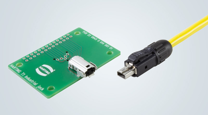
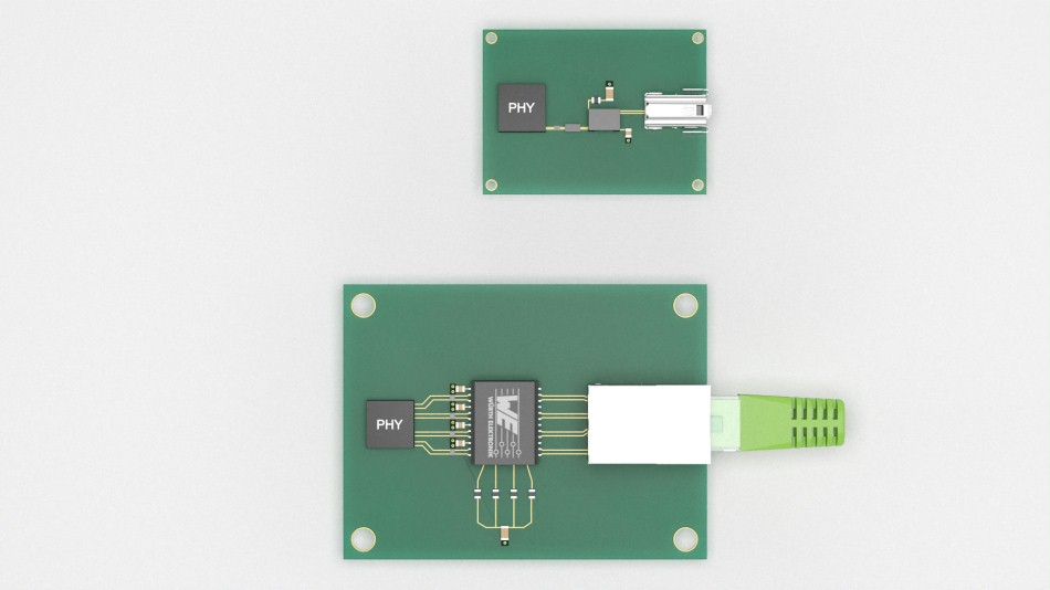
The result is a significant reduction in the required PC-board area for the connector pairing — often referred to as real estate or footprint compared to the standard RJ45 Ethernet connector (Figure 3).
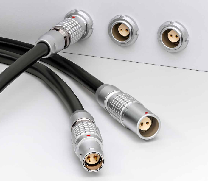
Note that vendors can offer other connectors as well. For example, LEMO (Switzerland) has introduced a snap-mate connector with a 1-Gbps rating which targets automotive, industrial, and other SPE applications (Figure 4).
The PHY electronics interface
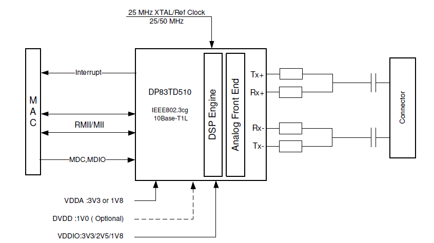
A physical link interface (PHY layer) consists of three parts: the cabling, the connector, and the interface electronics. In the very early days of electronics, this interface function might have simply been an electromagnetic relay (think telegraph), a vacuum-tube circuit (microphone amplifier), or discrete transistors. Today’s PHY interface circuitry requires an IC, of course. These ICs, in turn, connect to the system MAC (media access controller), which is often part of the larger host-processor device. For simpler interfaces, the PHY and MAC may be implemented in one IC, but at present, the PHY and MAC for IEEE 802.3 are separate components (Figure 5).

Recognizing the potential of SPE, IC vendors have developed suitable PHY devices. For example, the DP83TD510E SPE PHY transceiver IC from Texas Instruments (Figure 6) reaches up to 1700 meters, exceeding the baseline requirements of the IEEE 802.3cg 10Base-T1L sub-specification, which calls for 10 Mbps and up to 1000 meters through a single pair of twisted wire. In addition to its basic SPE functions, this 5 × 5 mm IC adds important features such as the defined safety and failure modes (important in industrial settings), EMI/RFI well below regulatory mandates, self-diagnostics, and more.
The transceiver is also compliant with IEC 61000-4-4, the International Electrotechnical Commission’s immunity standard based on electrical fast transient (EFT)/burst transients, CISPR22 radiated-emission class B mandates, and offers ±6-kV HBM ESD protection on its Media Dependent Interface (MDI) pins. Diagnostic tools include cable open/short-circuit detection; TDR (time domain reflectometry; ALCD (Active Link Cable Diagnostics); receiver SQI (Signal Quality Indicator) to measure cable degradation; multiple loopbacks; and an integrated PRBS Packet Generator to ease debugging during development and detecting faulty conditions in the field.
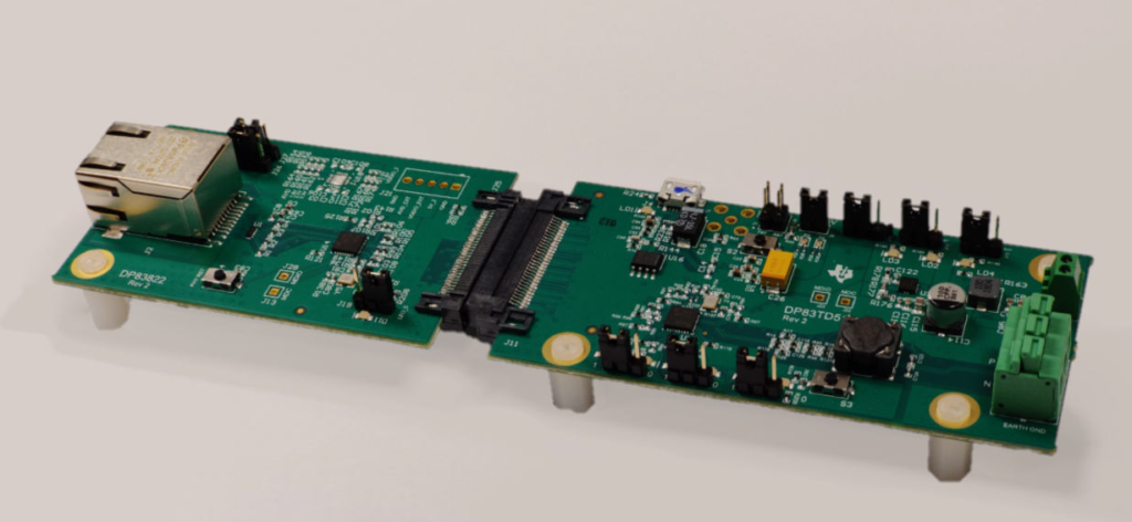
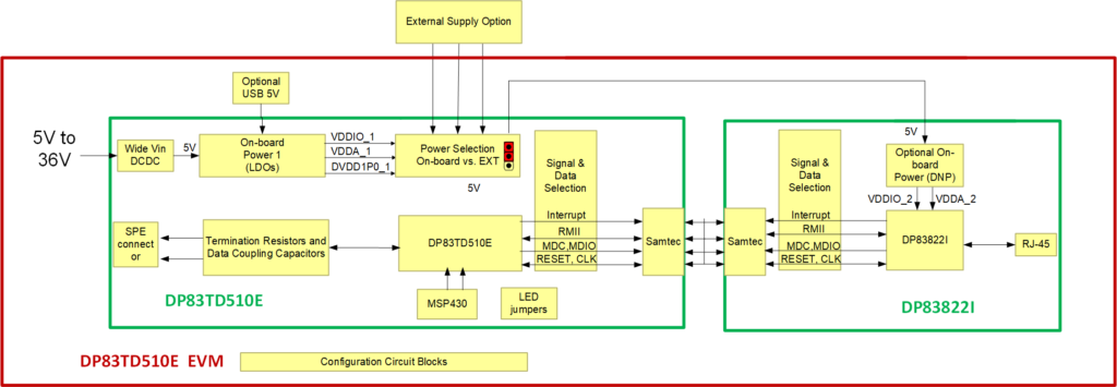
Setting up, evaluating, and optimizing an SPE design, like nearly all complex protocols, is not a trivial task (the IC’s datasheet runs 73 pages). For this reason, TI also offers the associated DP83TD510E-EVM evaluation module plus a companion DP83822I media converter board to provide 10BASE-TX Standard Ethernet support and enable bit-error-rate testing, interoperability testing, and compliance testing (Figure 7a and 7b). The module is powered by a 5-to-36 V power supply or through a microUSB cable and is supported by a 43-page User’s Guide.
Conclusion
While it may seem that more and faster are better, the reality is that less is actually more for some applications. A better fit with other application priorities — and in many cases, “good enough” is adequate while “more” is excessive. Single-Pair Ethernet (SPE), as defined by IEEE 802.3cg is a lower-cost, lighter, easier-to-deploy version of standard Ethernet with speeds that are sufficient for IIoT and other applications, while its longer reach is also a major advantage.
EE World Content
Single Pair Ethernet connector system paves way for IIoT applications
Molex joins Single Pair Ethernet Industrial Partner Network
Single-pair ethernet system targets commercial aircraft uses
Filter design includes galvanic isolation for single-pair Ethernet interface
1000 Base T1 single-pair Ethernet push-pull connector
References and Resources
IEEE Standards Association, “IEEE 802.3bw News release”
TIA/Single Pair Ethernet Consortium
Cabling Installation and Maintenance, “Single pair Ethernet: Data and power for the wired world”
Cabling Installation and Maintenance, “Single-pair Ethernet: The smart choice for intelligent buildings
Wikipedia, “Ethernet over twisted pair
Standards Informant, “IEEE Std 802.3cg-2019: 10 Mb/s Single-Pair Ethernet
Pepperl + Fuchs, “10 Mb/s Single Twisted Pair Ethernet10BASE-T1L and Clause 98
Harting, “Single Pair Ethernet – HARTING T1 Industrial
Wurth, “Single Pair Ethernet
LEMO High Speed Connector for Automotive Ethernet (1000BASE T1
Analog Devices, “Enabling Seamless Ethernet to the Field with 10BASE-T1L Connectivity
Texas Instruments, “How 10BASE-T1L single-pair Ethernet brings the network edge closer with fewer cables
Texas Instruments, “DP83td510e Data Sheet
Texas Instruments, “DP83TD510E-EVM User Guide

