Part 1 of this FAQ reviewed the standard PN semiconductor diode, and looked at some specialized variations called the tunnel, Zener/avalanche, and Schottky diodes. Part 2 briefly explores the varactor, Gunn, and PIN diodes.
Q: What about the varactor diode?
A: The varactor diode (Figure 1), also called a voltage variable capacitor (VVC) or varicap diode, is constructed and doped so that its capacitance varies as a function of the applied reverse-bias voltage. This is accomplished as follows: when the reverse voltage on the diode is increased, the width of the depletion region increases and the capacitance decreases; if the reverse voltage of the diode is decreased, then the width of the depletion region decreases and the capacitance increases.
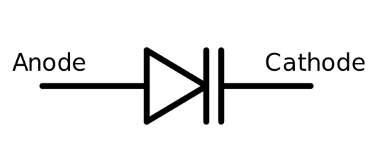
Fig 1: The most-common symbol for the varactor (varicap) diode. (Image: Slideshare)
Q: Why is this characteristic useful?
A: The varactor can be used to allow a voltage to adjust, trim, and fine-tune the resonant frequency of RF circuits, a feature often needed for precise tuning, calibration, or adjustment. The capacitance range is usually quite small, on the order of about 0.5 pF to 10 pF – but that’s enough to be significant at the RF frequencies at which it is being used.
Q: Does the varactor diode look like an ideal diode?
A: No, things are rarely that simple in the real world of solid-state physics and RF frequencies; (Figure 2) shows a simplified model of the varactor diode.
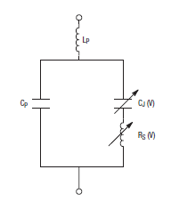
Fig 2: This simplified model of the varactor diode shows it is more complicated than just a voltage-dependent capacitor. (Image: Skyworks Solutions Inc)
Q: So many diode types – what about the Gunn diode?
A: The Gunn diode is based on an effect discovered in 1962 by physicist J. B. Gunn. It is not a “diode” in the conventional sense of having a PN junction, (Figure 3). Instead, it is composed of bulk N-type GaAs which is doped to have a negative-resistance effect, somewhat like the tunnel diode. Its more formal name is transferred electron device (TED), but that term is rarely used. Gunn diodes are now use a variety of base materials in addition to gallium arsenide (GaAs), such as indium phosphide (InP), gallium nitride (GaN), cadmium telluride (CdTe), cadmium sulfide (CdS), indium arsenide (InAs), indium antimonide (InSb) and zinc selenide (ZnSe). (It’s always useful to have a Periodic Table of the Elements handy when studying these devices!)
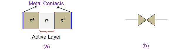
Fig 3: a) The Gunn diode has three n-type semiconductor layers, with the extreme layers heavily doped when compared to the middle, active layer; b) schematic symbol for the Gunn diode. (Image: Electrical 4 U)
Q: How does the Gunn diode function?
A: Up to about 1 V, the Gunn diode acts as a nearly linear resistor. However, as the applied voltage increases to a threshold voltage, the current no longer increases with increasing voltage. Instead, beyond this voltage, the diode has negative resistance which makes it the heart of a good oscillator. It is usually biased at about four to five times the threshold voltage.
Q: What is the Gunn diode used for?
A: The Gunn diode and its negative resistance aspect make it well-suited for oscillators at extremely high frequencies, from a few tens of GHz to beyond 100 GHz. You can buy standard Gunn-diode oscillators from many vendors for operation at these high frequencies. With a suitable heat sink, they can deliver tens of watts, which is otherwise difficult to provide at these frequencies. While the Gunn diode has the same two-terminal restriction as the tunnel diode, it provides a function that is otherwise often unobtainable via other approaches.
Q: I see the term “PIN diode” in RF and microwave circuits and literature; what is that?
A: The PIN diode’s designation stands for its three layers: “positive-intrinsic-negative,” (Figure 4). It is generally fabricated in either GaAs or silicon and used for RF switching; it is also very useful as a photodiode. It, too, acts as a variable resistor at RF and microwave (even millimeter-wave) frequencies. The RF impedance and on/off switching action of the PIN diode are determined by the forward-bias DC current.
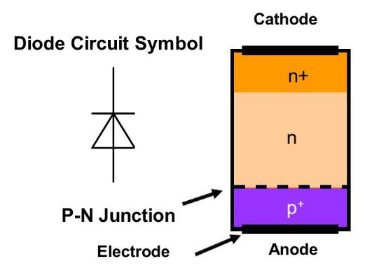
Fig 4: The schematic symbol and semiconductor structure of the PIN diode. (Image: ElProCus)
Q: Are PIN diodes widely used?
A: Yes, they are. When used as photodiodes, they are relatively easy to apply: just shine a photon source on the diode surface, and current flows from one terminal to the other, and use a transimpedance amplifier to capture and transform the current. However, they are much harder to use for RF switching, as they have the same shortcoming of all two-terminal switching devices: there is no separate control connection or port.
Q: Then how is the PIN diode managed?
A: As the PIN diode is a two-terminal device supporting DC and RF, external inductors and capacitors must be used with the PIN diode to properly combine, steer, and then separate the DC control voltage and the RF signal (Figure 5). Although the design is complicated with subtleties of these passive-component values, it is done because using the PIN diode as an RF switch has been one of the few options for non-mechanical RF-switching function. (Note, however, that new, non-PIN-diode solutions are now coming onto the market, using silicon and GaAs-based ICs; these are much, much easier to use and resemble conventional three-terminal electronic-switching elements.)
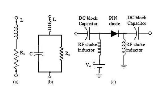
Fig 5: The equivalent circuit and configuration of PIN diode bias circuit showing (a) forward bias; (b) reverse bias; and (c) bias circuit which combines, then separates, the DC-control bias voltage and the RF signal being switched.(Image: (International Journal of Electrical and Computer Engineering – IJECE)
Q: You have mentioned several times the “two-terminal” switching problem which adversely affects the design-in challenge for some of these diodes. Can you clarify this, please?
A: In brief, here’s the problem: a three-terminal device such as a bipolar transistor or FET has a current input (its emitter or source connection), a current collector (or drain) connection, and controlling current or voltage port (base or gate). In contrast, for a two-terminal device, the DC control and RF signal-path connections are the same physical points. Therefore, they have to be managed as one composite signal at the diode but also as two signals when reaching or leaving the diode.
This FAQ has looked at various specialty diodes beyond the basic small-signal diode and power diode. Some of these diodes are no longer viable, some are widely used, and some are still used but seeing new alternatives – or for now they are the only viable option.
References
- Chennai Mathematical Institute (India), Ravitej Uppu, “V-I Characteristics of Diode”
- History-Computer, “The First Vacuum Tube”
- SchoolPhysics, “The thermionic diode”
- RF Café/Popular Electronics, “After Class: Working with Selenium Rectifiers”
- University of South Carolina, Department of Electrical Engineering, “Tunnel Diodes (Esaki Diode)”
- El-Pro-Cus, “Applications Involving in Zener Diode Working Functionality”
- Skyworks, “Varactor Diodes”
- Slideshare, “Varactor Diode”
- Electrical 4 U, “Gunn Diode”
- International Journal of Electrical and Computer Engineering (IJECE), “Miniature design of T-Shaped frequency Reconfigurable antenna for S-Band Application using Switching Technique”
- El-Pro-Cus, “PIN Diode Basics, Working and Applications”
- Microsemi/Microchip Technology Inc., “MicroNote Series 701: PIN Diode Fundamentals”
EE World Online References
- More options for SiC Schottky 1200-V diodes
- SPDT high-power PIN diode RF switches work up to 2.7 GHz
- What are diodes? A quick refresher
- What’s your type? Walk-thru of semiconductor diodes
- SPDT high-power PIN diode RF switches work up to 2.7 GHz
- SPDT PIN Diode Switches cover 10 MHz to 67 GHz range
- Gunn Diode oscillator operates at 24.125 GHz
- Meaning and measurement of negative resistance


Leave a Reply
You must be logged in to post a comment.