The DualSense wireless controller for the PS5 has several features that come in handy for gaming. Perhaps most interesting is its immersive haptic feedback and adaptive triggers. Dual actuators replace the rumble motors used on previous versions and  are designed to simulate the feeling of weapon recoils and numerous other game actions. Also included are adaptive triggers designed to let users experience varying levels of force and tension that are geared to what’s going on in the game, typical examples being pulling back an increasingly tight bowstring or hitting the brakes on a speeding car. There is also a built-in microphone for chatting with other gamers and a create button that lets users broadcast their adventures to their buddies.
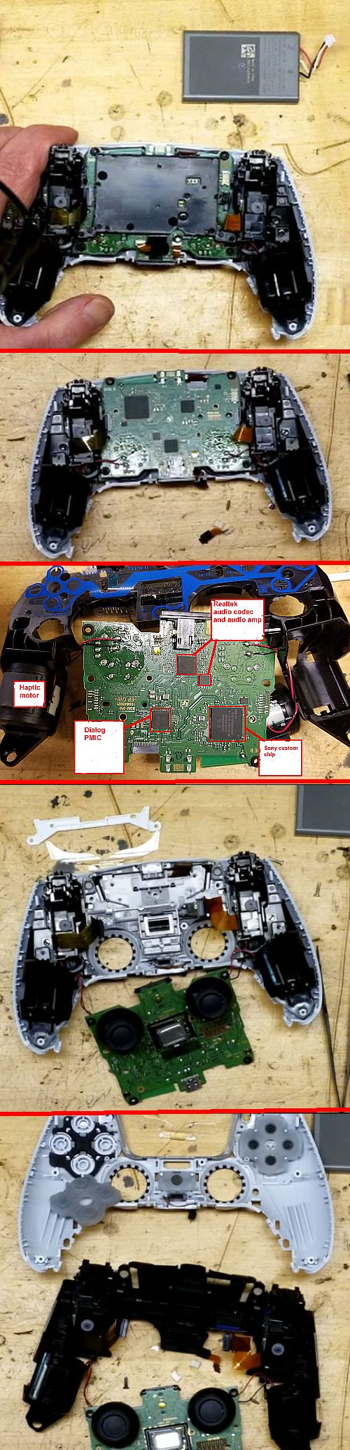
The disassembly begins by prying off a plastic trim cover which hide four Phillips screws. Removing them allows the removal of the top of the case. Visible beneath it is the 5.7-Wh lithium-ion battery, the haptics motors, and the adaptive trigger mechanisms. The battery attaches to the PCB via leads and a connector so it can be removed. Behind the battery sits the rear-facing microphone and the plastic well holding the battery, attached via another Phillips screw. Removing the plastic well reveals the motherboard.
The motherboard, joysticks, and haptics/vibration motors all sit in a black plastic frame. The joysticks are soldered to the motherboard. Observers report that these are the same type of joysticks employed on earlier PS controllers.
Much has been written about the shortcomings of game consule joysticks, including those on the PS5 controller. The principle
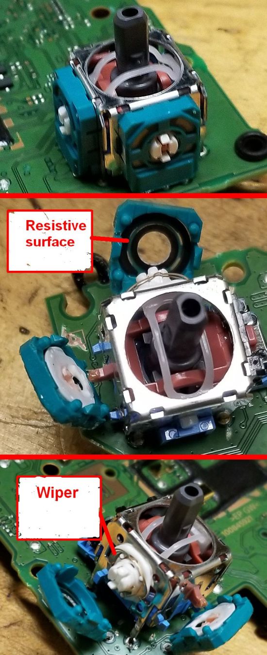
problem is these joysticks can drift and wear out after not all that much use. The principle wear-out mechanism seems to be two potentiometers that sense X and Y position. The potentiometers contain a metal wiper that touches a resistive surface. Over time, the resistive material can wear off and form debris that fouls the joystick sensing. The joystick also contains a spring that returns the joystick to a centered, neutral position when the user lets go. It has been widely reported that the spring-loaded self-centering mechanism can stretch slightly, creating a new “neutral” point. (As an aside, it would seem Hall effect non-contact position sensors might provide a longer life than wiper-based potentiometers. With all the engineering that went into the PS5 console, at least to us, it is unclear why the designers chose the direction they did with the joysticks.)
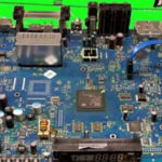
The motherboard contains four main ICs. One labeled SIE CXD9006GG is presumably a custom processor by Sony. A Dialog DA9070 PMIC chip manages charging, discharging, and power use and is specifically designed for wearables and home automation uses. A chip from Realtek labeled ALC5524 seems to be a custom version of an audio codec chip. The other chip is also from Realtek, an ALC1016, and seems to be an audio amp.
The purpose of the two Realtek audio chips may not have anything to do with generating sound. Though the controller has an integrated speaker, the audio chips may be there to power the haptics
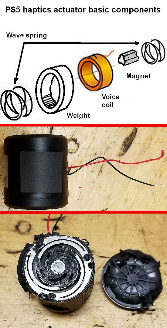
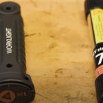
motors. Previous generations of PS controllers implemented haptics via old-style vibration motors which generated movement via eccentric masses rotated by ordinary dc motors. In contrast, the PS5 controller instead uses linear resonance actuators (LRAs) made by Foster in Japan (though they don’t have a regular Foster part number). The haptics motors attach to the black frame just via adhesive tape.
LRAs use a movable mass, permanent magnets, a voice coil and wave springs to generate vibrations. The voice coil produces a magnetic field which interacts with the permanent magnet, moving it in a way that compresses or stretches wave springs on either end of the vibration motor assembly. Thus where eccentric mass vibrators generate an effect on the end of a motor shaft, LRAs act more like the cone of a loudspeaker. The drive signal must be audio-frequency ac, hence the possible need for the audio amplifier/codec. The ac drive signal oscillates the magnetic field to make the permanent magnet move back and forth against the two wave springs, generating vibrations.
LRAs tend to be more sophisticated haptic vibrators than eccentric-mass motors. They typically exhibit shorter lag and rise times than eccentric motors, important for simulating short-duration effects. They also tend to consume less power. And it is possible to vary the amplitude and frequency of their ac input drive signals to realize complex waveforms and a richer user haptic experience than is possible with ordinary eccentric mass motors.
Also attached to the black plastic frame behind the motherboard are a white touchpad bracket and a clear light guide that
lets an LED on the motherboard provide lighting.
The black frame comes off with the removal of two screws from the frame arms. At this point the frame, motherboard, and vibration motors then can be removed from the other half of the outer case.
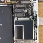
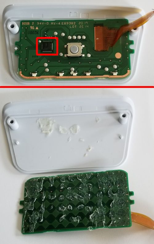
With the black plastic frame and circuit board removed, the touch pad becomes visible. There’s a PCB glued to the pad surface that doubles as the touch pad sensor. The PCB nestled behind the touch pad plate also contains the IC managing the touch functions, a Microchip ATMXT144U touchscreen controller. An interesting point to note about this chip is that it handles capacitive touch switches, but there’s also a simple on-off pushbutton switch on the touchpad PCB which it presumably handles as well.
Also residing on this part of the outer case are the eight button pads. The buttons themselves are on black plastic frame.
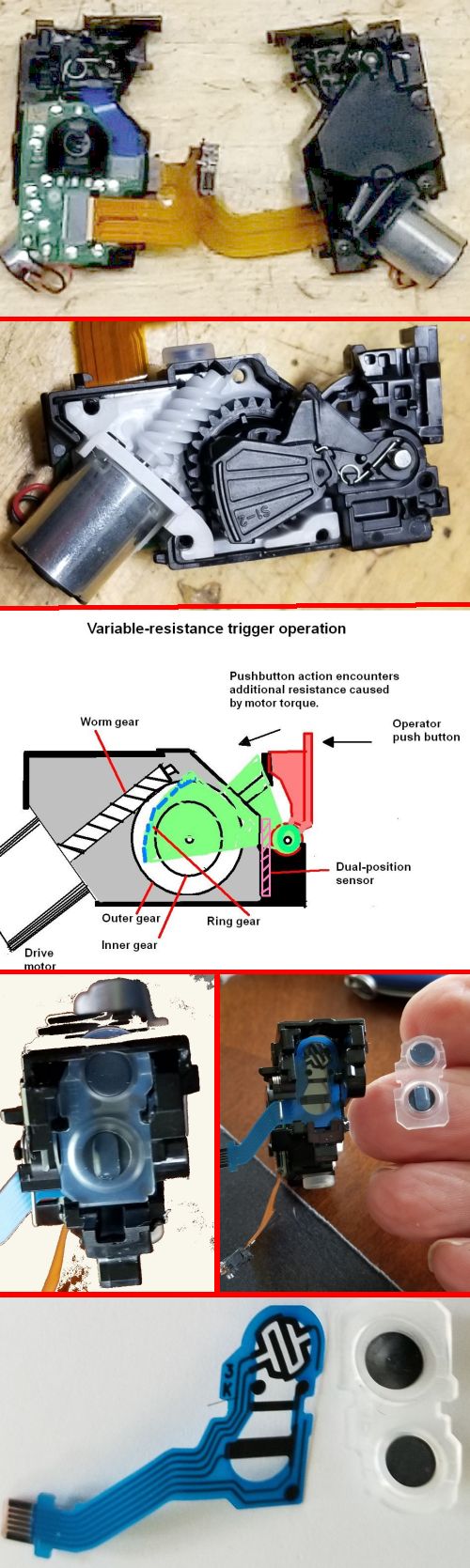
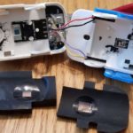
Two Phillips screws hold each of the trigger modules to the frame. Four other screws hold the trigger module case together. Removing them gives a view of the switches themselves and the mechanism used to vary the tension on the trigger lever.
The trigger modules feature a trigger-resistance that can be varied by the game software. This dynamic push resistance comes via a motor and worm gear that drives a gear-actuated plastic stop which pushes against the push switch. The farther the worn gear moves the stop, the more resistance applied to the push action of the switch. Basically, the added resistance comes from pushing against the motor torque as applied through the worm-gear/gear/ring-gear combination. The gear set position is recorded via a potentiometer on the module PCB. An unlabeled IC on the module PCB seems to be handling the switch functions.
Interestingly, the right-hand module differs from the left-hand module. Inside the right-hand module is what seems to be a two-position sensor able to detect both partial and full trigger pulls. In contrast, the left-hand module contains a simple on-off switch.
And those are the high points of the PS5 controller.