 If you’re recovering from a respiratory problem, chances are you may have had your oxygen levels checked with a pulse oximeter. Pulse oximetry is the non-invasive measurement of the oxygen saturation (SpO2). Oxygen saturation is defined as the amount of oxygen dissolved in blood, based on the detection of Hemoglobin, Hb, and Deoxyhemoglobin, HbO2.
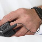
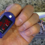
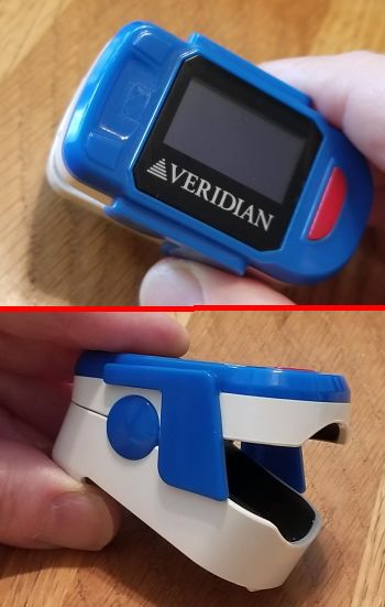
The typical pulse oximeter is a device that clamps on one of your fingers. Home-use oximeters are often battery-powered and self-contained with the oxygen level displayed on a built-in LCD along with heart rate. That’s the kind we tore down, made by Veridian Healthcare in Illinois. Before we get into how it works, some background in how a pulse oximeter works is in order.
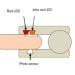
Pulse oximeters use two different light wavelengths, 660 nm (red light) and 940 nm (infrared light), to measure the difference in the absorption spectra of HbO2 and Hb. Hb absorbs light at 660 nm and HbO2 at 940 nm.
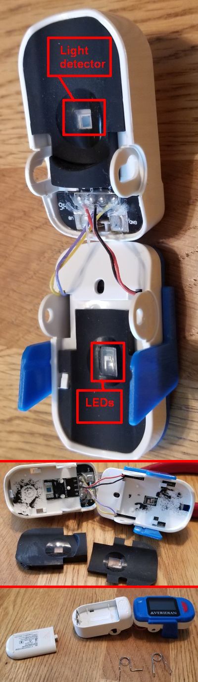
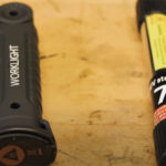
Top, removing the springs allows a view of the LEDs and light detector positioned on either side of the finger. Middle, removing the pads gives a better view of the LEDs and detector. Bottom, the Veridian pulse ox is powered by two AAA batteries that sit on the bottom half of the device.
A photodetector in the sensor gauges the non-absorbed light from the LEDs. This signal is typically inverted using an inverting op amp, and the result is a signal that represents the light that has been absorbed by the finger. It is divided into dc and ac components. The dc component represents the light absorption of the tissue, venous blood, and non-pulsatile arterial blood. The ac component represents the pulsatile arterial blood.
The pulse oximeter analyzes the light absorption of two wavelengths from the pulsatile-added volume of oxygenated arterial blood and calculates the absorption ratio using:

SpO2 is typically taken from a table stored in memory calculated with empirical formulas. A ratio of 1 represents a SpO2 of 85%, a ratio of 0.4 represents SpO2 of 100%, and a ratio of 3.4 represents SpO2 of 0%.
Another way for calculating SpO2 is by taking the ac component and determine ratio using
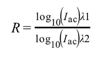
SpO2 is the value of RX100. Iac = Light intensity at λ1 (660 nm) or λ2 (940 nm), where only the ac level is present.
The output generated by the photodetector is a current that represents the light absorption. This current typically gets converted into a voltage for filtering and then measurement.
There’s not much to the typical pulse oximeter circuit described in most literature. It runs via an MCU that does the calculations and generates the PWM signal to drive the LEDs. And that’s what Veridian does in its pulse oximeter. The heart of the device is a Silicon Labs C8051F007 mixed-signal SoC MCU with a 12-bit multi-channel ADC. Among its features are a
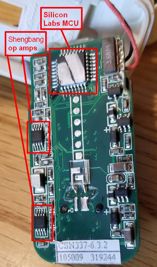
The back of the PCB holding the LCD contains the MCU and two of the op amp ICs for signal conditioning.
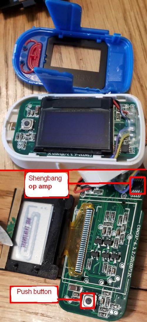
The pulse ox with the screen bezel removed, top, and with the LCD flipped up to reveal the numerous discrete components mounted to the PCB beneath it, bottom.
programmable-gain pre-amp, two 12-bit DACs, two voltage comparators, a voltage reference, and an 8051-compatible MCU core with 32 kbytes of Flash memory. There are also four general-purpose 16-bit timers and four byte-wide general-purpose digital port I/O. The chip has 2,304 bytes of RAM and executes at up to 25 MIPS.
The only other chips on the PCB are three CMOS op amp devices from Shengbang Microelectronics, probably used for filtering the light detector signals.
And that’s pretty much it for the simple pulse oximeter which also measures heart rate.
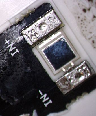
A close-up of the light detector used to sense LED light.