Robotic race cars make clever use of software and infrared optics to follow lines slyly hidden on the track.
Leland Teschler, Executive Editor
The Overdrive starter kit we analyzed contains sections of track that can go together in various ways and can even include jumps. An interesting feature of the track is that its sections use magnets to click together, and the track can be configured in a variety of racing layouts. To flawlessly traverse every layout thrown at it, each car takes a training lap before a race and basically memorizes the track using a built-in optical sensor to sense track position.
The cars are powered by rechargeable lithium batteries, and the set comes with a recharging station where cars sit until their batteries are ready.

Under the covers
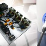
It is worth examining how the motors are probably controlled. (One widely followed teardown site analyzed the Overdrive cars and botched the explanation of components related to the motor control, probably because those involved didn’t really understand motor control techniques.)Removing the top of a car exposes the circuit board, the chassis, and a large ballast weight. The PCB sits in the chassis sandwiched between the two halves of the car shell so it comes out easily. Once it’s out, the mechanism by which the car steers becomes clear. There’s no steering mechanism. Instead, the car uses two tiny electric motors, one to power each of the rear wheels. So the car steers by slightly increasing or decreasing the speed of each rear wheel as need be.
To begin, the speed of the motors can’t be controlled precisely enough to steer the car without some kind of closed-loop control. The reason is that just putting in a specific amount of motor current won’t guarantee that the motor will spin at a precise velocity. There can be changes in the tire friction as the car moves, as well as other variables that can slightly change the motor speed.
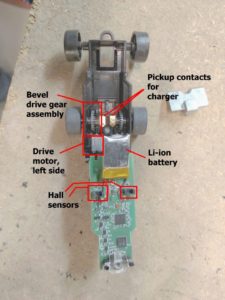
To make sure each motor spins at exactly the right speed, the controller must measure the speed of rotation of each axle. That is what the Hall effect switches do. Each motor drives a wheel through a bevel gear. The teeth of the driven gear pass next to a Hall effect sensor which is used as a way to sense wheel velocity. Pulses generated when individual gear teeth pass by the Hall sensor get fed back to the motor controller as a measure of wheel speed.
Sensed wheel speed is used to generate an error signal or correction factor for the speed command sent to the motor. In the case of these cars, the motor controller is an STM microcontroller that has motor control capabilities built in. The STM controller notes the speed of the axle and compares it to the speed it has commanded the axle to turn. The difference between the commanded speed and the actual speed is an error term. If that error term is growing bigger, the controller speeds up the motor slightly by sending it more current.
If the error gets smaller, the controller slows that motor slightly. To make sure each motor spins at exactly the right speed, the controller must measure the speed of rotation of each axle. That is what the Hall effect switches do. Each motor drives a wheel through a bevel gear. The teeth of the driven gear pass next to a Hall effect sensor which is used as a way to sense wheel velocity. Pulses generated when individual gear teeth pass by the Hall sensor get fed back to the motor controller as a measure of wheel speed.
The method by which the controller knows when to change the speed so it can turn the car is also interesting. It involves the clever way that Anki devised the track the cars race around. The track viewed in normal light looks to be almost solid black. But when viewed through the right type of infrared filter, a pattern emerges. It is this pattern that the cars see. The pattern basically consists of lines which the cars follow. There are a series of dashes with varying width that are situated alongside the lines. The dashes seem to be there as a means for the car to notice that it’s getting too far away from the solid line it is trying to follow.

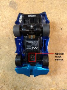
The car sees those lines via an optical sensor chip and an infrared LED at the front of each car, along with a lens assembly. The lens assembly does two things. First, it routes the light from the infrared LED down to the track to illuminate the spot that the optical sensor looks at. Second, it focuses the sensor on the track so the car can follow the line. The method by which the controller knows when to change the speed so it can turn the car is also interesting. It involves the clever way that Anki devised the track the cars race around.
The track viewed in normal light looks to be almost solid black. But when viewed through the right type of infrared filter, a pattern emerges. It is this pattern that the cars see. The pattern basically consists of lines which the cars follow. There are a series of dashes with varying width that are situated alongside the lines. The dashes seem to be there as a means for the car to notice that it’s getting too far away from the solid line it is trying to follow.
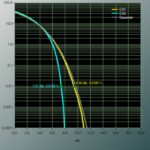
We have an image of the track taken through a blue filter that lets near infrared light be imaged. This image comes from Travis Deyle who founded the robotics website called Hizook. Travis has graciously let us use it.
The rest of the components on the PCB are relatively straightforward. They include a low-energy Bluetooth chip from Nordic Semiconductor. We’ve seen it used on several other consumer devices. Additionally, there is a battery charging chip from Linear Technology. We also found four Diodes Inc. chips containing complementary pairs of MOSFETs, and a few other no wideband bipolar transistors.

One might also note what is not on the circuit board: You might think the Overdrive cars have light sensors or other electronics for detecting light from another car, as would happen when a car is hit by one of the numerous “weapons” in the arsenal.

But there are no sensors on the chassis other than the one used for finding lines on the track. Instead, the software just actuates LEDs placed at various points on the car’s circuit board to help reinforce the illusion that the car has been hit by a tractor beam, a laser blaster, or some other misfortune. In that regard, the Anki team did a remarkable job of instilling their system with enough realism to keep things interesting.
References
Diodes Inc. DMG 1016G complementary pair enhancement mode MOSFET,
Linear Technology Inc. TP4054 lithium battery charger IC,
Nordic Semiconductor nRF8001 BLE,
Philips BF547 npn 1 GHz wideband transistor,
STMicroelectronics STM32F051K8 motor control MCU,