Press a button on the wall and a wireless connection tells this LED bulb what to do.
Leland Teschler
Executive Editor
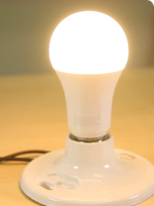 A NEW LED BULB from the furniture maker Ikea of Sweden is called the TRÅDFI. Now available in Europe, it’s expected to hit the U.S. soon. It comes with its own remote controller which mounts to the wall and uses a wireless connection to switch the bulb on and off, adjust bulb color temperature and dimming level.
As smart LED bulbs go, this one is pretty simple. It doesn’t incorporate any sort of smartphone app and can’t be controlled over the Internet, like some other smart bulbs we’ve seen.
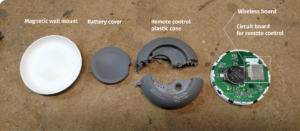
The remote which controls the LED bulb has what seems like an elegant way of mounting to the wall. A base for the remote attaches to the wall either with screws or adhesive. Then the remote itself fits into the base, held on with a magnet. This scheme lets the user remove the remote to change its battery when the need arises and gives the wall-mounted remote a sleek look. The battery is a CR 2032, a widely available 4.3-V lithium coin cell.
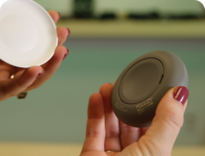
The Ikea TRÅDFI LED bulb can be dimmed and color-controlled from a remote switch that communicates with the bulb wirelessly. The remote switch is magnetically attracted to a base (far left) that mounts on a wall. The magnetic attraction lets the switch be pulled down for replacement of its coin-cell battery.
The Ikea bulb talks to the remote in a way resembling that used by many other smart bulbs: The designers put the wireless chip on a separate circuit board that solders to the main board holding the driver electronics. In the case of the Ikea bulb, the wireless board mounts perpendicular to the main LED driver board with solder connections between the two on the edge of the wireless board.
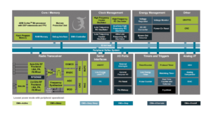
Block diagram for the wireless chip (EFR32MG1) from Silicon Labs in Austin, Tex.
The identical wireless board also resides in the wall switch. In both the LED bulb and the wall remote, the wireless chip (EFR32MG1) is from Silicon Labs in Texas. This chip handles several wireless protocols that include BLE, ZigBee and Thread. Unfortunately, we have no way to identify which of these the LED bulb uses. The chip is a system-on-a-chip device that includes a 32-bit ARM controller, a radio transceiver, I/O ports and serial interfaces, as well as numerous other peripheral functions. In fact, the chip integration is such that the only other items on the wireless board are a few passive components and a printed circuit antenna, which pokes out through a hole in the LED plate.
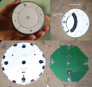
Not much to see. The bottom images show the back of the remote control’s PCB containing the switches and the plastic wall switch containing the conductive rubber contacts. We removed one of the switch plates (top) to show the conductive elastomer contact point.
The wall switch disassembled.
Though the wireless board mounts on edge in the LED bulb, it sits flat against the main circuit board inside the wall-mounted bulb controller. The control’s main circuit board primarily holds the wireless board and the battery holder and serves as a substrate for the switch pad. The switch pad itself is a straightforward design where pressing a switch pushes down on a conductive rubber contact that, in turn, touches the circuit board to signal a button push.
Bulb architecture
A point to note about the wireless board in the bulb is that there are only six soldered connections between it and the LED driver board. Assuming power and ground account for two of them, that means there are perhaps just four leads available to control the LEDs. In addition, there is no way to tell whether the wireless board on the remote is identical to that on the bulb; system-on-chip devices can be made with a variety of different options.
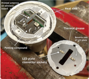
Cutting off the acrylic bulb reveals the LED board. Visible here is the slot through which the wireless board antenna pokes through. Also evident are the two connectors used to mate the LED board with the bulb electronics – unusual in that most bulbs just use soldered connections. Removing the LED board reveals the thermal grease used between the plate and the heat sink and the connector pins to the LED plate, coming from the epoxied electronics in the bulb base.
The bulb has a physical layout that’s widely used for LED bulbs. It employs a 2.4-oz. heatsink that surrounds a circuit board potted in flexible epoxy-like material. The epoxy also provides some structural rigidity to the base of the bulb and the electrical contacts. The main circuit board and all the epoxy potting material fits inside a plastic sleeve that, in turn, slides inside the heat sink.
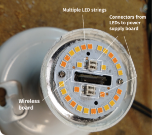
Visible here is the slot through which the wireless board antenna pokes through. Also evident are the two connectors used to mate the LED board with the bulb electronics – unusual in that most bulbs just use soldered connections. Also note LEDs that are light amber and dark amber. Dark and light LEDs are in separate strings, likely done as a way to implement color temperature changes and dimming.
The 28 LEDs on the bulb reside on a single metal plate that helps conduct heat and sits on the 2.4-oz. heat sink. Thermal grease sits at the interface between the LED plate and heat sink.
Interestingly, this is the first LED bulb we’ve torn down that uses mechanical connectors, rather than just two soldered wires, for a connection from the circuit board to the LED plate. In fact, the Ikea bulb uses dual connectors which each take the form of two pins extending from the main circuit board that mate with a simple contact on the LED board.
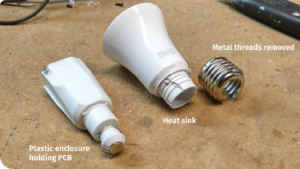
Bulb electronics all fit in a plastic sleeve (left) that slides into the heat sink (right).
We surmise the reason the bulb uses two connectors, rather than just one, is because the LEDs on the bulb are wired as two separate strings, one on each connector. That’s different than on most bulbs – most just wire all their LEDs in series in one long string.
The rationale for two strings becomes clear from a close examination of the LEDs: There seem to be two different kinds. One style has a slightly darker amber color than the other. So the two strings evidently are wired so they can be operated independently. And that’s probably how the LED bulb manages dimming and changing its color temperature. It judiciously lowers or raises the current to either of the two strings to modulate both the amount of light output and probably the color temperature as well.
However, the use of two LED strings presents a problem from the standpoint of driver design. Because most LED bulbs only use one string, most LED driver chips for use in LED bulbs can drive just one LED string. A bulb carrying two LED strings can’t easily use a driver chip designed to handle just one.
Though there are numerous chips available for driving multiple strings of LEDs, the applications most of these chips address are in LCD backlighting or related display-type uses. They really aren’t set up for light bulbs. So they really aren’t appropriate for what Ikea is doing with this light bulb.

The bulb PCB doesn’t contain a standard LED driver chip, but components found on the board seem to indicate the use of separate buck converters for each of the two LED strings, and for use of active power-factor correction. The wireless chip had metal shielding which has been removed in the top image.
And that reality probably explains why the Ikea bulb doesn’t seem to contain a standard controller chip. There’s an unmarked eight-pin chip that seems to be handling LED control. Our guess is that it’s based on an LED driver design that was modified to handle two LED strings, but its source can’t be discerned from its markings.
To analyze the LED drive, we can look at the other components on the circuit board and make educated guesses about the driver topology. Starting with the primary side of the circuit, we find five large capacitors near the diode bridge and a power transistor, but no inductors. One possibility is that the transistor is there for purposes of power factor correction (PFC). And most LED bulbs these days do incorporate PFC, though we couldn’t find any power factor specs for the Ikea bulb.

Components found on the bulb PCB seem to indicate the bulb uses active rather than passive PFC.
The fact that there are no big 60-Hz inductors in the primary side of the circuit tends to eliminate the possibility that PFC takes place passively. Most passive PFC circuits use bulky inductors, and it could be problematic to squeeze them into the base of an LED bulb along with everything else that must fit there. That’s why most LED bulbs go with active PFC if they do it at all.
Moving past the circuitry near the base of the bulb, a large transformer resides on the circuit board that is likely part of the driver circuit itself. We might surmise from this setup that the transformer is there basically to isolate the secondary side of the circuit and to divide the input power into the two portions used by each of the LED strings.
To determine the topology, we note that the circuit on the other side of the transformer consists of identical pairs of components, as when there are two channels of LEDs. The fact that we find dual sets of these components tends to affirm the idea that the two LED strings are independently driven and controlled. The circuitry for each channel includes a power FET, an inductor, two sizeable capacitors, two beefy diodes, and a six-pin chip too small to be identified by its markings.
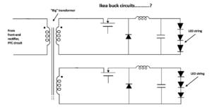
Components on the bulb PCB might indicate that the LED driver topology is that of dual buck converters, one for each of the LED strings, driven through an isolation transformer.
The question becomes, what kind of a converter could employ these particular components? The most obvious answer would seem to be a buck converter. This topology steps down voltage while stepping up current. And it typically contains at least a diode and a transistor and at least one energy storage element such as an inductor. To reduce voltage ripple, it might incorporate a filter comprised of capacitors. So the buck converter would be our guess as to what we’re dealing with here.
All in all, Ikea has put out an LED bulb that seems to work pretty well for those who only need something that responds to a nearby light switch. It’s not a candidate for those who want to dim or otherwise control a bulb over the cloud for some reason.
References
Silicon Labs EFR32MG1 Mighty Gecko SoC