Ketra unapologetically charges $100 for its A20 LED bulb, and the bulb needs a controller to work. Here’s what you find inside the bulb that makes it worth the premium price.
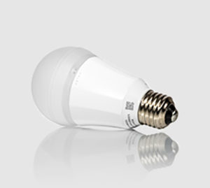 A tunable A20-style LED light bulb from Ketra, in Austin, Tex., may be the world’s most expensive classic LED bulb. It lists at about $100 and needs a controller, sold separately, to work. Ketra’s bulbs mimic the natural lighting of their surroundings and can be configured to change their color temperature to do things like produce the glow of a sunrise or recreate sunset light, all while being completely dimmable down to zero light output. A separate wall-switch controller and configuration software communicates with the LED bulb over a zigbee wireless link. But the bulb will also dim from a conventional wall dimmer switch. In that case the dimming waveform from the wall switch takes precedence over any dimming command the bulb has received wirelessly.
Obviously, this is a high-end bulb. You’d only be likely to find it in lighting designed by architects or specialized lighting designers. But you might wonder what’s inside Ketra’s bulb that lets it get that super-wide range of color temperature and versatile dimmability. One reason for such versatility is a special controller chip that Ketra designed. This chip is proprietary so we can’t say exactly how it operates or how the bulbs manage some of their tricks. But we can make some assessments about the approach Ketra designers took in creating their bulb.
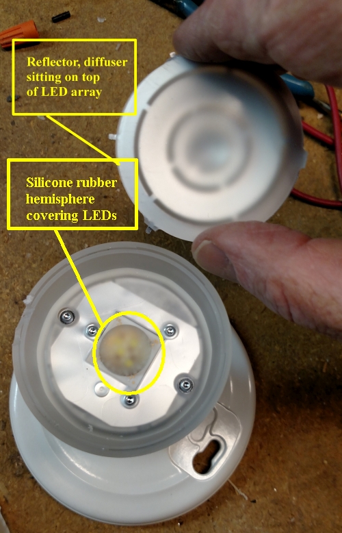
Cutting off the polycarbonate dome revealed louvers for light mixing as apparently described in a Ketra patent. Visible as well is a silicone rubber-like hemispherical dome over the LEDs and light sensors.
The first interesting aspect of the Ketra bulb is the way the LEDs are configured. They sit on a metal plate as is generally the case with most LED bulbs. But they all sit inside a small hemisphere of silicone rubber-like material in the center of the plate. We’ve never seen an LED plate configured this way before. Most other LED bulbs contain LEDs that are scattered around the plate. But on the Ketra bulb, putting the LEDs in this small area concentrates their light. Then there are diffusers and reflectors inside the polycarbonate bulb dome that shape and sort of modulate the LED light.
Also, the LEDs you find on the Ketra bulb are much, much smaller than those LED bulbs use. A typical LED in a bulb generally measures on the order of about an eighth of an inch square. The 20 LEDs in the Ketra bulb measure roughly half that size or even less.
A look the LEDs shows how the Ketra bulb manages to get a wide range of color temperature. The usual way of getting an LED bulb to put out different color temperature is to use different kinds of LEDs, each operating at a different color temperature. And that seems to be what Ketra did here. We found what seem to be three different kinds of LEDs on the board.
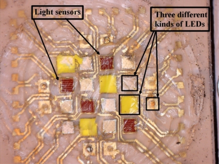
A close-up of the LEDs with the elastomer dome cut off reveals three different types (R, G, and B?) and three light sensors.
Ketra’s product literature says the bulb’s light color gets measured 360 times a second to ensure the light output is right. Apparently, those measurements happen thanks to four light sensors we found mounted among the LEDs on the plate.
Also, a look at one of Ketra’s patents reveals that the light sensors are there to adjust illumination levels for different temperatures and to compensate for LED aging. The patent mentions turning on LEDs one at a time, then measuring the output of each in turn to make adjustments in drive levels as need be.
Additionally, the polycarbonate dome holds a diffuser and a metal reflector with strategically placed slits. In its patents, Ketra calls this reflector a louver. A Ketra patent sheds light – so to speak—on the louver’s purpose. It is help mix the colors from the various LEDs. The patent claims louvers focus a majority of the light emitted by the LEDs into an output beam. The louvers allow the portion of the light that emanates sideways from LEDs to mix underneath before beaming out.
Inside the base
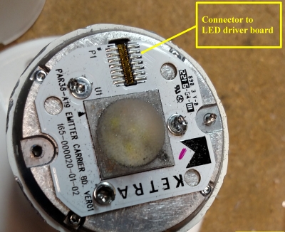
The LED plate and connector. Also note: No hole needed for the zigbee PCB antenna.
Also interesting is that the LED plate attaches to the bulb electronics through a connector. Most less expensive LED bulbs just solder wires from the PCB to the LED plate.
Another noteworthy point about the LED plate is that there’s no hole in it for a wireless antenna. Most LEDs that contain wireless transceivers have a PCB antenna poking out through a hole in their LED plate. The reason the Ketra bulb doesn’t need a hole in its LED plate is that the antenna is oriented in the other direction, toward the base of the bulb.
Specifically, the zigbee board attaches to the LED driver PCB via a connector. The LED driver PCB, along with the zigbee board, is surrounded by a 1.4-ounce heat sink that seems to have been die cast out of pot metal. The metal plate holding the LEDs attaches to the bulb end of the heat sink. Consequently, the zigbee wireless board sits so it is mostly surrounded and enclosed by the metal heat sink and metal LED plate. The zigbee PCB antenna pokes out just past the lower edge of the metal heat sink – far enough, apparently, so the metal of the heat sink doesn’t stop the antenna from radiating.
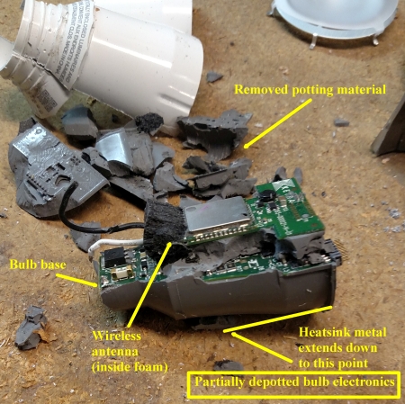
Partly depotted electronics revealing the foam wrapped around the PCB antenna on the zigbee board.
Ketra avoided another potential problem with its wireless circuits when it used epoxy potting material on its bulb electronics. The entire LED board is potted inside a plastic housing. Potting is a common technique in LED bulbs. The potting material gives the LED some extra structural rigidity and serves as a way of enhancing the thermal conduction to the bulb’s metal heat sink.
But there’s a problem with potting compound from the standpoint of radio frequency transmissions. Potting material severely loads any antenna it touches. So an antenna covered in potting compound just won’t radiate well and conversely, it won’t pick up the microvolt-level signals potentially coming from a zigbee transmitter.
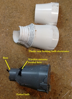
With the potting material still in place and the board removed from its plastic shell, the foam covering of the PCB antenna is visible poking out near the bulb base.
Ketra got around the antenna loading problem by wrapping a piece of foam around the portion of the wireless PCB containing the zigbee antenna. The foam is there specifically to keep the epoxy about a quarter of an inch away from the antenna.
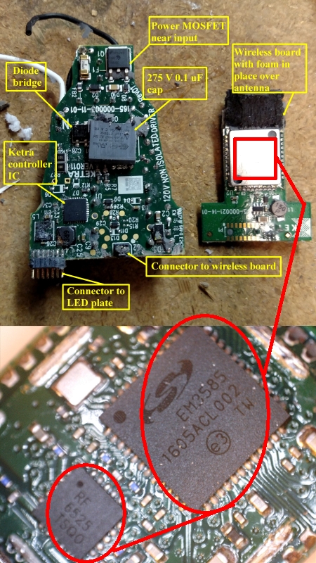
The depotted LED driver and wireless boards, top, and a close-up (bottom) of the Silicon Labs wireless chip and Qorvo RF amp found inside the metal shield.
Ketra did one other thing to make sure there are good wireless connections to the bulb. The wireless board in the Ketra bulb contains two ICs. The main chip is a Silicon Labs EM3585 zigbee mesh transceiver. The second chip is a front-end module from Qorvo that provides 11.5 dB of gain for received signals and 28 dB of gain for transmitted signals. That’s a sizeable boost. So it basically looks as though Ketra took out some insurance to make sure zigbee signals had enough oomph to get through the potting material and around the metal formed by the heat sinks.
That brings us to the topology of the LED driver circuitry. Ketra uses its own proprietary controller IC so we can’t be sure of exactly how the LEDs are powered. But we can make a few guesses based on Ketra’s patents.
Specifically, Ketra patented a technique for driving LEDs from a triac wall dimmer switch. Ketra measures the phase angle of the incoming ac waveform to check for the action of a dimmer. It uses this information to set the dc current going to the LEDs.
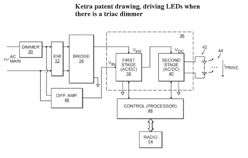
Overall block diagram from Ketra’s triac dimmer-handling patent.
The patent describes the circuit that does this as consisting first of control loop (slow loop) and a second control loop (fast loop). The first control loop includes an output-integrating capacitor and a loop-stabilizing proportional-integral (PI) filter. The output of the loop filter represents the average current drawn from the ac main line measured over more than one ac cycle. A high-bandwidth first-order loop within the main control loop (i.e., second control loop) ensures that the actual power supply current roughly equals dc supply current during each conduction angle in which the dc power supply is active.
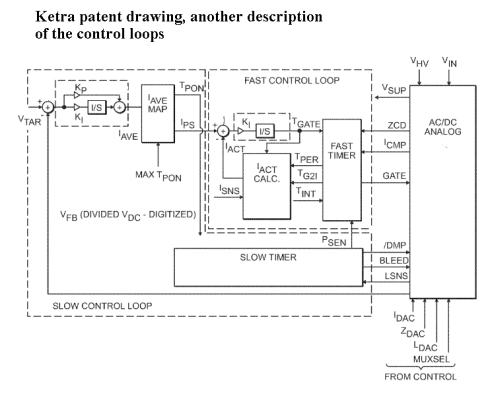
The fast and slow loops as described in a Ketra patent.
A control circuit measures the conduction angle from the dimmer. Conduction angle, apparently, is used as a signal to the bulb processor. That’s because the bulb is designed to let any triac dimmer action override any commands received over the wireless zigbee connection.
The second control loop has a higher bandwidth than the first control loop. The second loop controls the pulse-width modulated pulses that normally control switching power supply circuits.
Of course, the controller dictates the LED brightness levels based on the triac conduction angle it sees. The patent says the parameters can be stored in firmware or periodically updated through read/write memory via wireless control.
All in all, the Ketra controller chip generates the PWM signal for the power supply topology based on either parameters beamed in over zigbee or measured from an ac waveform clipped by a triac dimmer. It also controls the color temperature of the bulb by selectively modulating the brightness of different LEDs on the LED plate. Finally, it seems to compensate for aging LEDs by periodically measuring the lumen output of each LED and comparing it to the measured forward voltage.
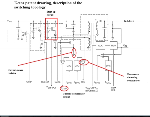
The flyback topology as described in the Ketra patent relating to LED control when there’s a triac dimmer involved.
The topology used to drive the LEDs seems to be that of a flyback converter. That is the topology discussed in one of the Ketra patents. Some of the physical details were obscured by the potting compound. Nevertheless, the magic of the Ketra bulb’s operation seems to be in the Ketra controller chip rather than in the specific topology used to drive the LEDs.
The full description of the converter that the patent describes gets quite involved and goes beyond the scope of what we’re presenting. But here are a few highlights:
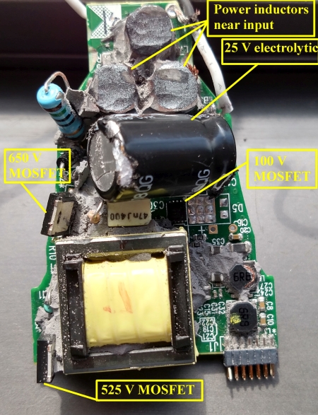
Visible on the depotted main LED driver board are what may be the flyback transformer mentioned in the Ketra patent, along with three different power MOSFETs, and three power inductors sitting near the ac input to the board.
According to the patent, the flyback converter comprises a transformer with primary and secondary winding. When the gate signal is high, the primary winding conducts and current through it rises linearly with time. A current-sense resistor and comparator produces a current comparator output which indicates when the primary current reaches a certain value set by a parameter from the control circuit processor. The fast timer uses the current comparator output to determine when to turn the gate off. When the gate goes low, the primary current drops to zero and the energy stored in the transformer core produces current in secondary winding. The secondary winding current flows through a diode and into a bypass capacitor and then to the LED load.
A small portion of the energy stored in the transformer core produces current in an auxiliary winding that passes through a diode and into capacitor. Once all the energy stored in the core is depleted, the current in both secondary winding and auxiliary winding stops flowing and the voltage across both windings collapses. A zero-crossing detect comparator and its corresponding DAC detect this collapse and set the comparator output to a logic high value. The fast timer uses this rising edge of this comparator output signal to set the gate high, starting another power supply computation cycle.
Markings on the LED circuit board say this is a non-isolated driver. Board components of note are a big transistor and a 0.1 µF capacitor rated for 275 V near the input, along with three relatively large inductors that are obviously storing some energy, based on their rather beefy size. Also, there’s a MOSFET near the input that looks big enough to handle the whole current load of all the LEDs. One possibility is that the inductors and the MOSFET might be handling power factor correction.
That brings us to the output part of the circuit. Evident on the board are two beefy MOSFETs that seem to be sitting in the secondary of the driver. But they are not identical. They have slightly different voltage and current ratings. And there is a third MOSFET in that area from a different manufacturer which has ratings that differ from the other two.
Because we found three different kinds of LEDs on the bulb, you might expect to find three identical driver circuits in the secondary of the power supply. But that just isn’t the case. We might speculate that the differences may reflect the slightly different forward voltages and current carrying behavior of LEDs having different color temperatures.
All in all, the topology of the bulb is quite interesting given that there are three separate LED strings.


Leave a Reply
You must be logged in to post a comment.