5G Technology World visits Northeastern University’s Ultrabroadband Nanonetworking Lab for a firsthand look at what’s possible in wireless data communications.
In 6G Symposium emphasizes business and technology, we reported that while 6G technology is still in the research lab, people are talking about use cases. This comes even though 5G is in its early stages of use cases. Whatever the use cases, we’ll need another air-interface technology to move beyond 5G. That’s were university research labs such as the Ultrabroadband Nanonetworking Lab at Northeastern University in Boston play a role. 5G Technology World recently visited the lab for an inside look, shown through photos and videos.

Professor Josep M. Jornet
Professor Josep M. Jornet, a speaker at the 6G Symposium, along with colleagues Tommaso Melodia, Kaushik Chowdhury, Francesco Restuccia, and Milica Stojanovic guide a team of students, ranging from first-year undergraduates to PhD candidates, in many aspects of 6G research. Jornet focuses on developing the terahertz air interfaces needed to carry enough data in and out of networks. Just having an air interface isn’t enough, which is why the professors also focus on signal processing and data networks. “Sending bits won’t do,” said Jornet, “you have to send intelligent data.”
Terahertz frequencies are roughly defined as starting above 100 GHz. The TeraNova test bed shown in Figures 1, 2, and Video 1 consists of three transmitter and receiver pairs that operate from 120 GHz to 140 GHz, 210 GHz to 240 GHz, and 1 THz to 1.1 THz. The transmitter in Figure 1 uses a Keysight PSG analog signal generator to generate carriers from 30 GHz to 35 GHz. The frequency multiplier system from Virginia Diodes (the plate behind the red cylinder housing the antenna) multiplies the signal frequency by four to reach 120 GHz to 140 GHz. Because the point of digital communications is to send and receive data, a Keysight M8196A arbitrary waveform generator produces an analog signal that carries digital information. The waveform generator can generate signals with up to 32 GHz bandwidth. That’s more than can fit into the 120 GHz to 140 GHz carrier signal. The frequency multiplier also mixes the data signal and carrier. The modulated signal then goes to the directional lens antenna, which contains a horn antenna. The red case keeps the signal on target.
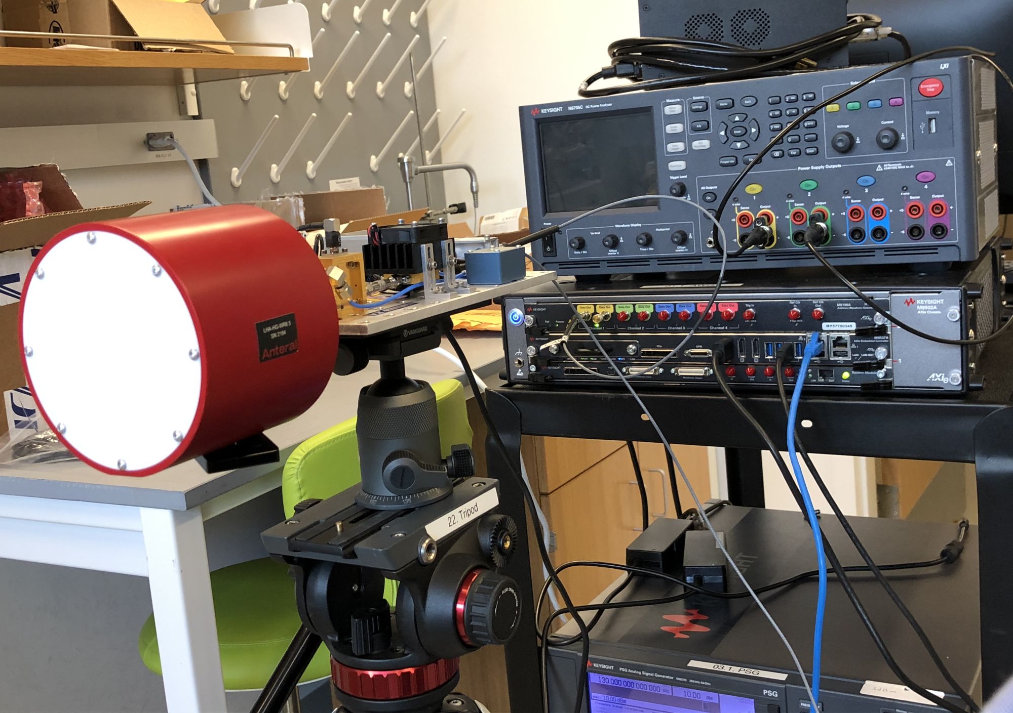
Figure 1. The TeraNova testbed transmitter sends bits to a receive using 120 GHz to 140 GHz carrier frequencies.
The receiver (Figure 2) uses a horn antenna connected to a its own frequency multiplier, which generates the same 120 GHz to 140 GHz signal needed to demodulate the signal. The mixer removes the carrier, leaving the data signal. A Keysight DSOZ632A oscilloscope digitizes and saves the signal for offline processing. The team is developing a signal-processing FPGA board to generate and interpret data in real time.
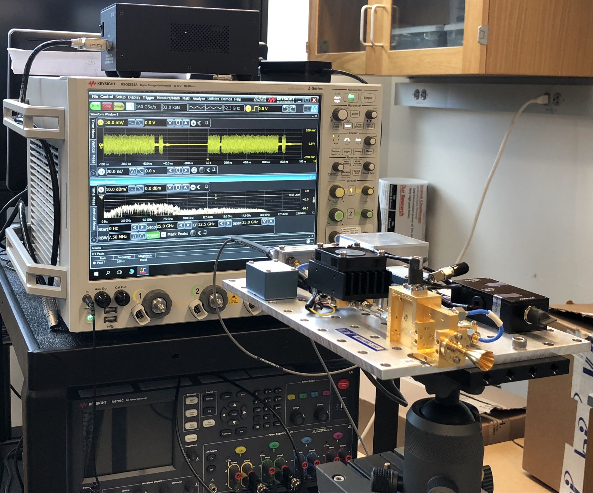
Figure 2. The TeraNova testbed receiver also consists of a frequency multiplier, connected to an oscilloscope.
As part of its terahertz-frequency research, the team uses another frequency multiplier that delivers frequencies from 1 THz to 1.1 THz. The Virginia Diodes systems are frequency multiplying chains. The 120 GHz to 140 GHz is a 2×2 chain while the terahertz frequency multiplier uses a 2x2x2x3 chain to get 24x. At 1 THz, the transmit signal power is less than 100 µW. The 1-THz system uses a horn antenna housed in a protective case (Figure 3) for mechanical stability.
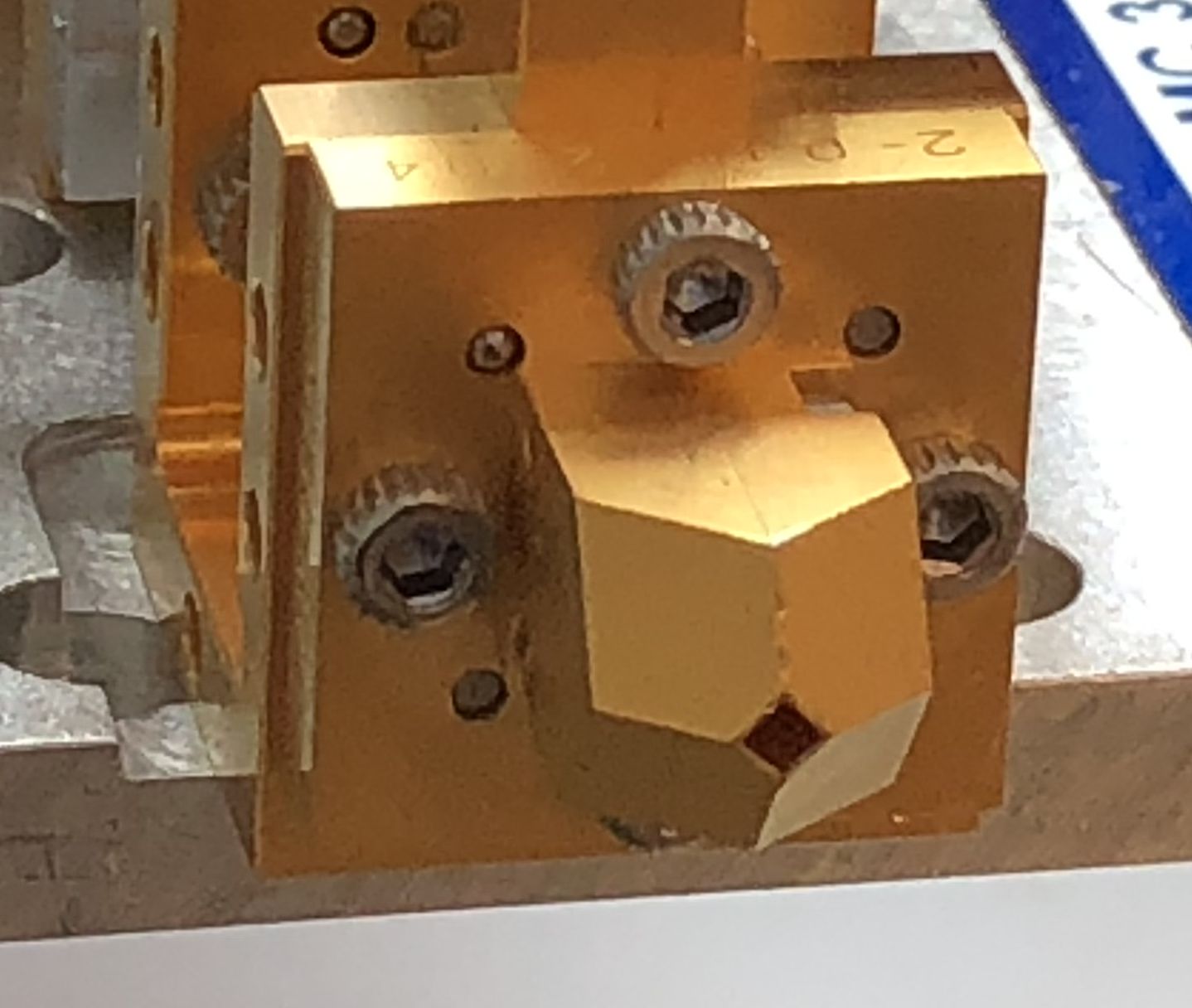
Figure 3. A terahertz horn antenna resides inside this protective metal housing.
The system in Figure 4 operates at 210 GHz to 240 GHz uses components from NASA and Quantum Microwave. This a high-power (200 mW) frequency multiplier has two 3x multipliers and work from 210 GHz to 240 GHz.
Because the TeraNova testbed uses I/Q modulation, researchers looked at several constellations to see how they perform at these frequencies. Using Matlab, students can take the oscilloscope’s digitized signal and plot constellation diagrams (Figure 5). “We can use any constellation at terahertz frequencies,” said Jornet.
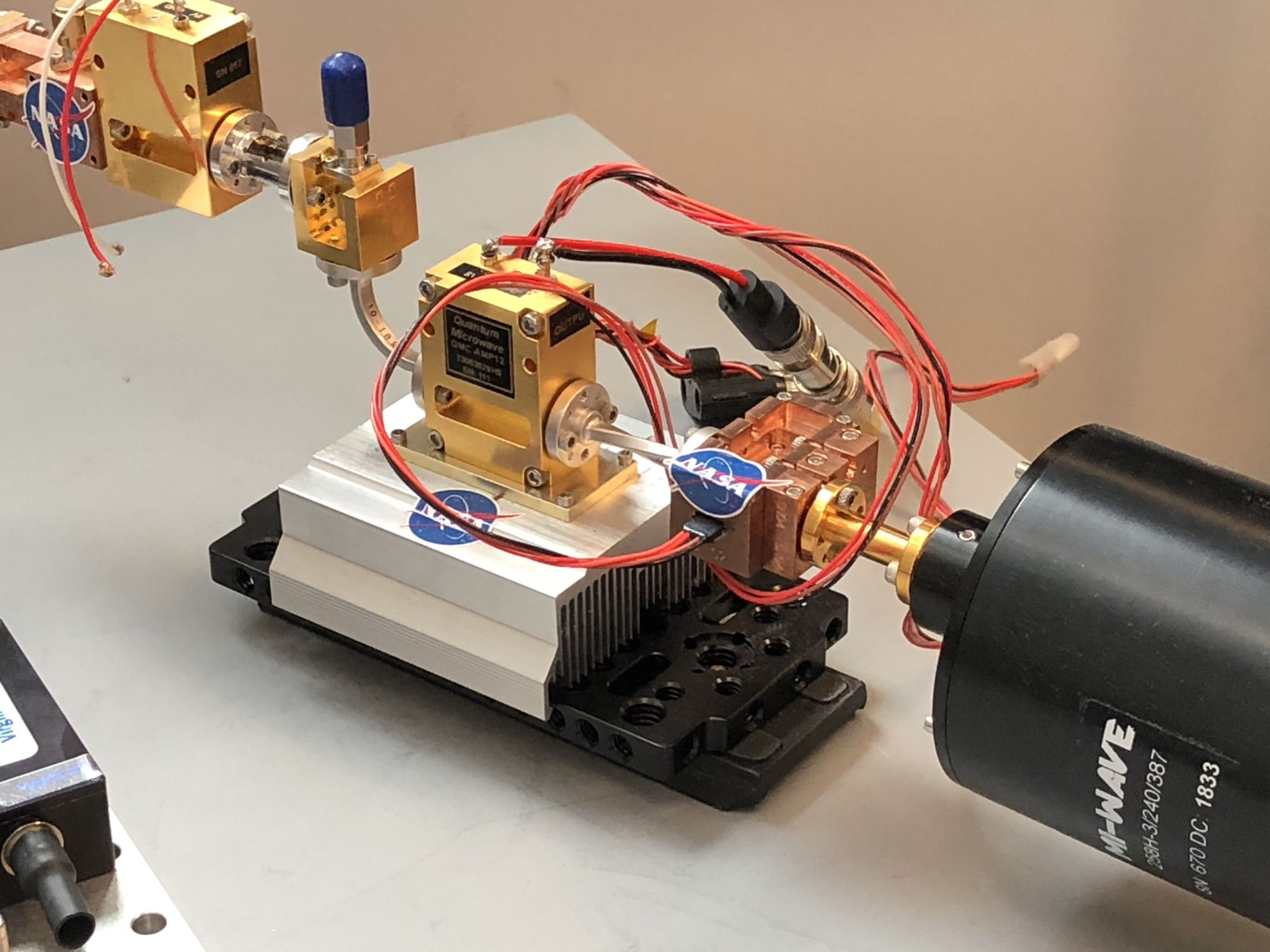
Figure 4. A NASA-provided system sends data over 220 GHz to 240 GHz carriers.
Signals at such high frequencies suffer from degradation as they travel from a transmitter to a receiver. A reflecting dish concentrates the signal and amplifies it to improve signal strength. The dish in Figure 6 can provide 50 dB of gain at 1 THz. A first-year undergraduate student, supervised by a senior PhD student who specializes in terahertz antennas, designed the dish and its holder. “We try to involve students from the very beginning,” said Jornet. “They want to go beyond just taking courses.”
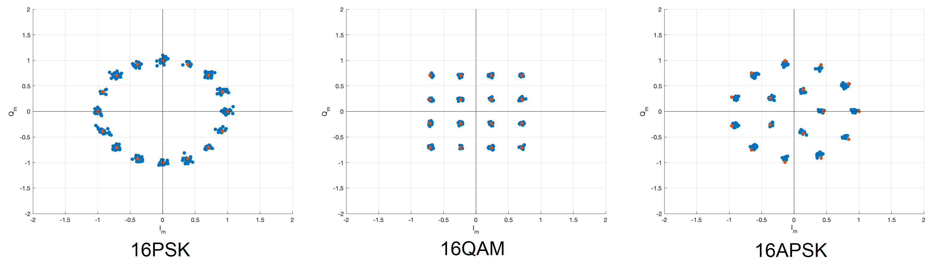
Figure 5. Constellation diagrams of terahertz signals show that any modulation should work at terahertz frequencies.
The researchers need to move data in real time, something they can’t do with the system in Figures 1 and 2. To achive real-time performance, they’re developing functionality for the FPGA board in Video 2, which wasn’t connected during our visit. The board contains a Xilinx RF SoC. The board’s FPGA performs signal processing on four I/Q pairs. Each pair gets filtered and mix with an I/Q mixer that creates four signals at slightly different frequencies. The frequency combiner creates a single signal with four frequency components, each carrying data from an I/Q pair. The composite signal then goes to the Virginia Diodes system for transmission. The FPGA board replaces the arbitrary waveform generator for transmitting and the oscilloscope for receiving. The board lets the research team send real data and interpret received data in real time. PhD student Hussam Abdellatif, together with a former postdoctoral researcher in the group, wrote the signal-processing code for the FPGA.
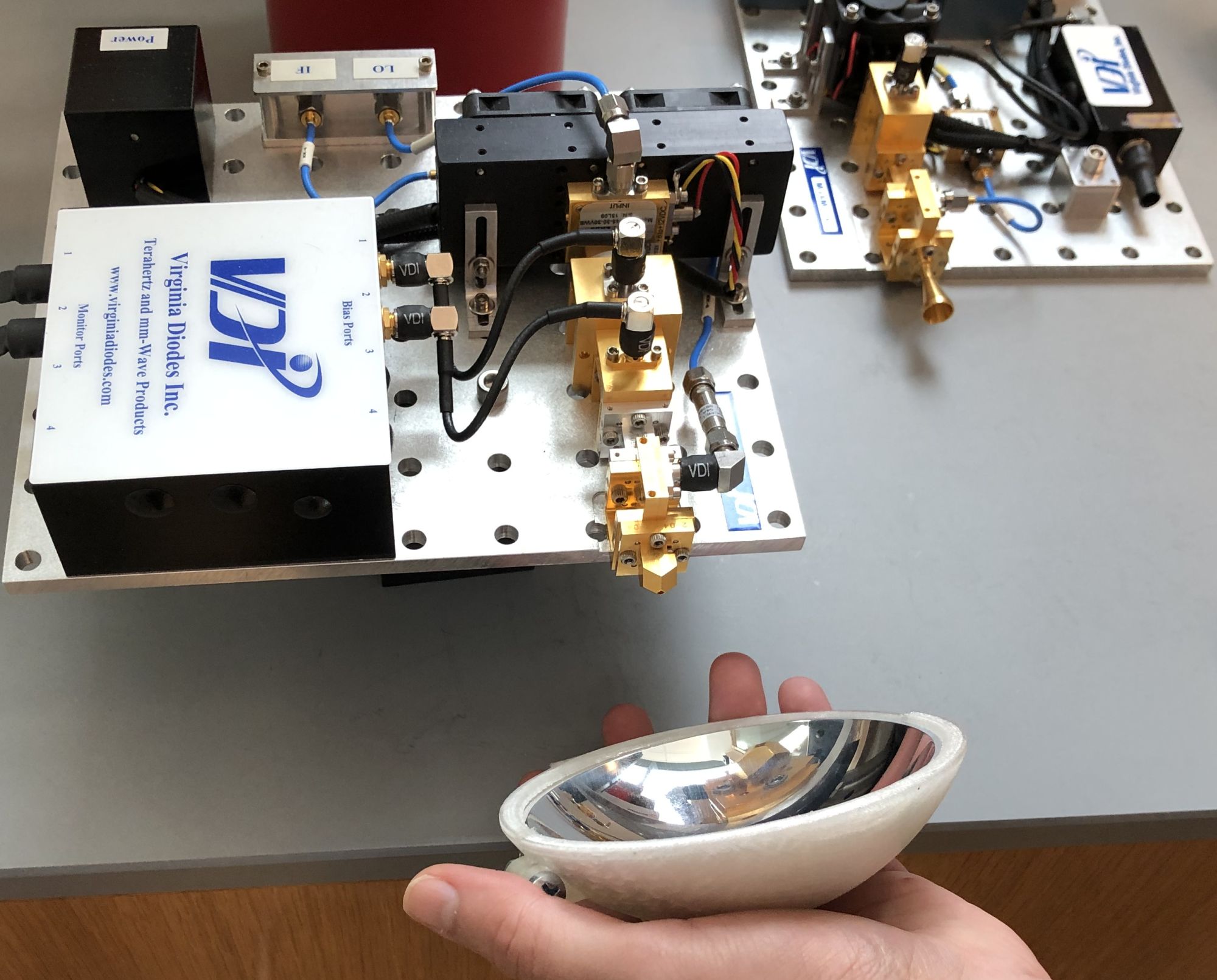
Figure 6. A Student-designed reflecting dish amplifies at 1-THz signal by 50 dB.
We’re still several years away from the first 6G specification and perhaps ten years away from deployment. Only then will we have an idea of possible use cases, though the talk at recent conferences indicates that 6G will focus on consumers as where 5G specifications show promise for industrial uses.