Connectors and cabling can be as important as the test instruments used to check out systems operating in the 5G realm.
John Muzzio, Times Microwave Systems
Andrew Dinsdale, SV Microwave
Unlike previous cellular technology generations that were focused on a specific frequency band, 5G deals with a much larger potential frequency range. For example, 4G frequency bands are typically below 3 GHz. 5G on the other hand can range from 450 MHz to 3.9 GHz and includes 20-52.6 GHz millimeter-wave bands for high-speed operations. 5G also encompasses unlicensed frequency bands, such as the 6 GHz band.
This broad span of frequencies has introduced new challenges for 5G testing including repeatability, reliability, and reproducibility. As is the case with any RF testing, measurements require unique coaxial cable and connector setups— and it is critical to ensure signal integrity for RF interconnects. Measurement repeatability is key as these systems are connected and disconnected often. The connectors and cables must withstand extensive handling, and the materials they employ must be optimized.
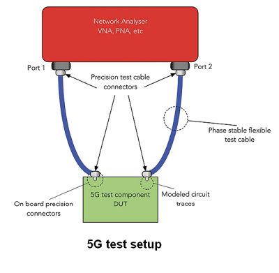
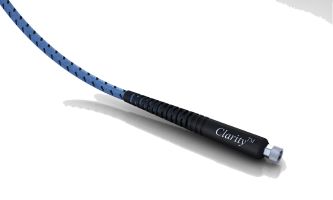
The testing process typically involves a device-under-test connected to a vector network analyzer (VNA), oscilloscope or spectrum analyzer. The signal path from the instrument to the circuit board is critical, and the user must ensure the test setup–including the test cable assembly, cable, adapters, and board mounted connectors–does not introduce unwanted variables.
Many product developers working in 5G are dealing with a new frequency range that is unfamiliar, and the cables and connectors they’ve traditionally used will no longer work. For example, many RF test labs working in 4G LTE are outfitted with sub-10-GHz VNAs and associated test leads and accessories using Type N or 7/16 connector interfaces. To handle the full 5G spectrum, they must invest in not only expensive RF instruments, but also millimeter-wave test cables, adapters and board-level interconnects that can accommodate higher bandwidth without compromising signal integrity.
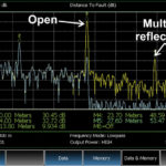
When a signal transitions from the PCB to the connector, it is imperative to minimize reflections. At higher frequencies, imperfections in the transition from a coaxial connector to a circuit board structure become more apparent. These imperfections can cause parasitic and spurious signal responses. They manifest as return loss or insertion loss, spikes, and other undesirable effects. If the signal integrity is off and there is noise in the measurement, the test results won’t be accurate.
High-fidelity measurements demand a repeatable, low-insertion-loss cable that functions throughout the desired frequency range. Similarly, a board-level product should be matched to the circuit board at the launch to ensure low return loss.
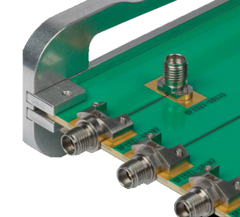
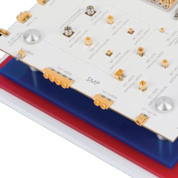
For board-level products, millimeter-wave connectors offer a secure, threaded connection and can operate mode free in 5G frequencies (2.92-mm dc-40 GHz, 2.4-mm dc-50 GHz, 1.85-mm dc-65 GHz, and 1.0-mm dc-110 GHz). Push-on connectors such as SMP, SMPM, and SMPS connectors are candidates for applications involving high signal density.
Phase control is another parameter for optimizing system
performance in 5G smart antennas. Electronically steered antennas use multiple antenna arrays and vary the phase relationships among them to control the radiation pattern. This technique allows, for example, switching from a search radiation pattern to a tracking radiation pattern, or shifting the direction of radiation quickly. The arrays are fed by transmission lines; beam accuracy depends upon the phase relationships among the signals in those cables. Phase must be accurately controlled in the components within those systems, making phase-stable cable assemblies important.
The super-short wavelengths characterizing the 5G frequency range imply that even short lengths of cable handling 5G signals span a lot of wavelengths at those frequencies. Differences in impedance over the cable length, though they are typically minuscule, make it tough to maintain phase accuracy.
Cables can be phase-matched in pairs or groupings. But as temperatures warm or cool, the cables may not exactly track together; the signals they carry can go slightly out of phase. That small amount of degradation, known as the cable phase tracking characteristic, reduces antenna performance. To minimize such phase problems, phase-stable cables typically contain a TF4, or microporous PTFE dielectric, coupled with a helically wound metalized interlayer.
High density
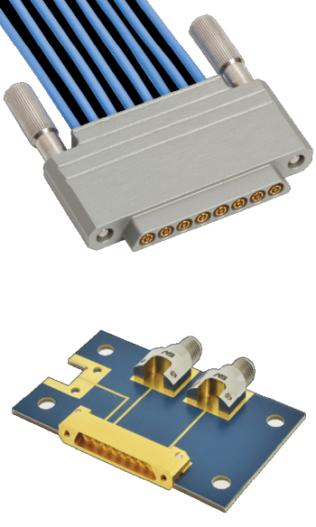
5G specifications are based on the use of MIMO technology requiring multiple arrays of transmit and receive antennas. To accommodate larger bandwidth requirements, more antennas are squeezed into smaller spaces. This trend leads to use of high-density interconnections, such as multi-pin connectors and mini-coaxial cable bundles, between the antennas and the radios. Use of high-density multi-port connectors additionally allows testing to take place next to the DUT, shortening distances involved in testing and reducing the chance for interference.
Also important is the use of flexible cable material that can be easily positioned on a test bench, either in R&D or during production. Testing often moves from module to module. At 5G frequencies, every movement of a module or cable could require a recalibration. However, a cable that can bend and flex will greatly reduce the amount of recalibration required while maintaining stability.
Frequency, time delay, and physical properties such as length, dielectric constant and propagation velocity all affect electrical length. Coaxial cables are constructed with a consistent dielectric material throughout the length of the cable that creates a constant velocity factor. Though the material is consistent, environmental and handling factors can alter the cable electrical properties–like temperature fluctuations, flexure, twisting, pulling, and crushing–during installation and maintenance.
The metals used in cables expand as they heat up and contract as they cool. Similarly, the dielectric constant expands and contracts as well, and its density changes, altering the signal velocity. The dielectric effects of the plastic offset and dominate the metal effects. The materials used to ensure phase stability and amplitude include PTFE dielectric, which allows for good signal transmission.