Designers integrating USB Type C and USB4 into their products confront several challenges to ensure interoperability and compliance. Compared with previous generations, the latest USB specifications are more demanding due to higher power and more complex power profiles, higher data transmission speeds, and more functionality in general. To address these challenges, test engineers must start with accurate and standard-compliant test instrumentation, software, and fixtures.
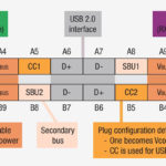
USB Type C power delivery (USB PD) is more complex, including 5 specifications ranging from 10W to 100W. The latest USB PD specification includes variable power scenarios, bidirectional power, and ALT mode for devices that are not compliant with USB PD powering protocols. USB hosts, devices, and accessories negotiate power delivery capabilities via the USB PD communications protocol that is executed on the new configuration channels (CC1 and CC2). The CC1 / CC2 line signals need to be verified for correct protocol transmission for dynamically changing power and managing ALT modes.
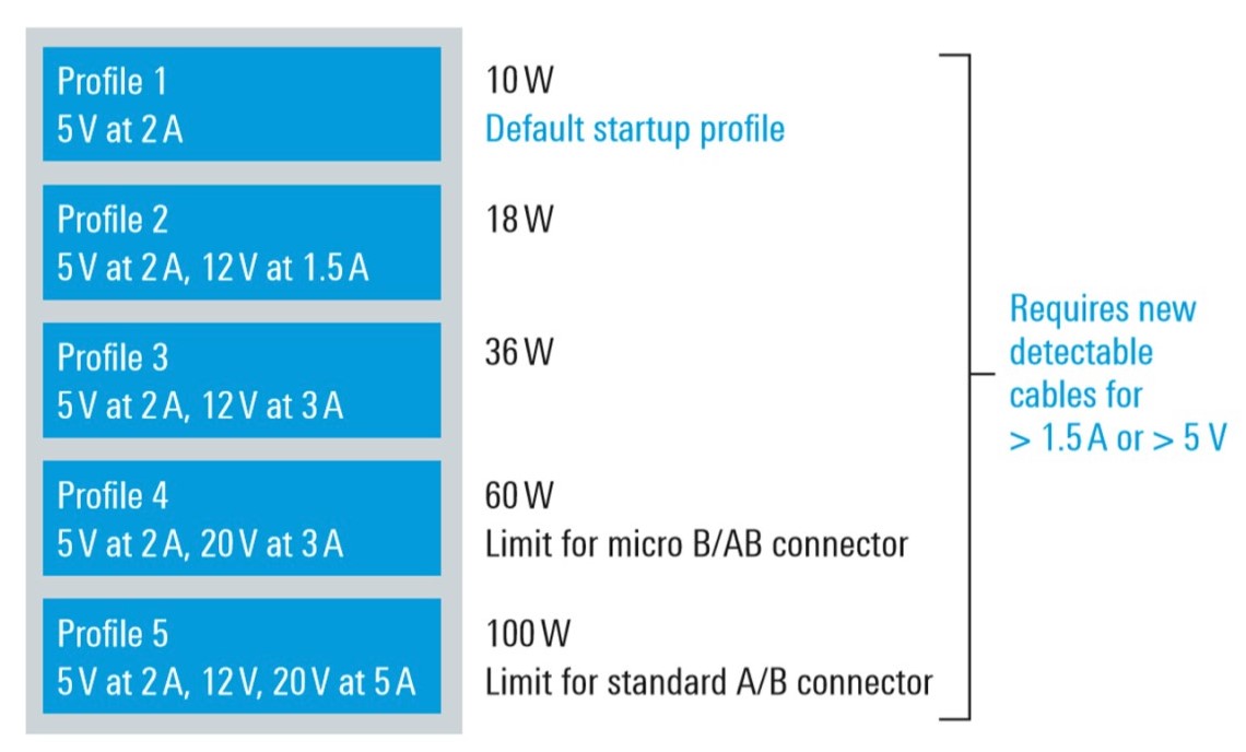
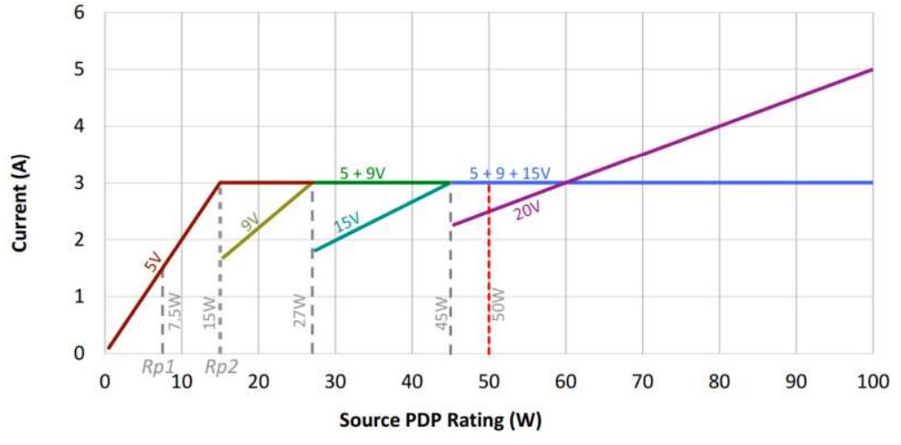
The latest USB PD specification v3.0 supports the higher and dynamically variable power. It is implemented by initially increasing the VBUS voltage while maintaining a current of 3A. The discrete voltage levels supported are 5V, 9V, 15V, and 20V. After reaching the maximum voltage of 20 V, the current can be increased up to 5A. For a given power level, a source must support all previous voltages and power levels. A 60W source meeting the new USB PD profile (PDP) specification must be able to supply 20V, 15V, 9V, and 5V, all with 3A of current. This requirement is intended to ensure that a higher wattage power source, for example, a laptop charger, can also support lower wattage (and lower voltage) devices such as a mobile phone handset.
The complexities of the latest USB PDPs require that designers spend more time dealing with performance verification and testing to ensure compliance. Additional challenges relate to maintaining backward compatibility with previous generations of USB power specifications.
Full-featured USB Type C adapters and cables are electronically marked (e-mark) and include an identification function chip that is accessible through the CC interface. Testing the e-mark functionality is now part of the USB Implementers Forum (USB-IF) USB PD compliance test specification.
USB PD 3.0 Fast Role Swap testing
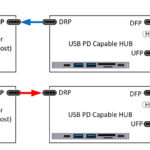
USB PD 3.0 fast role swap (FRS) is designed to reduce the risk of data loss for USB peripherals due to an unexpected removal of a dock or hub power cable. It keeps devices powered, even if the dock or hub they are connected to loses power. Implementing FRS requires a precise and rapid exchange of messages between the dock/hub and the device being powered. FRS supports power delivery role swapping within 150μs. USB PD 3.0 chipsets and devices that support FRS are required to pass specific compliance testing. FRS tests are only required for dual-role power (DRP) ports. A DRP port can function as a power source or sink and may alternate between those states.
When a DRP initially operates as a source, the port takes the data-role of a downstream-facing port (DFP) and sends data downstream; it is often the port on a dock or a hub to which devices connect. On the other hand, when a DRP initially operates as a sink, the port takes the data role of an upstream-facing port (UFP), which connects to a hub or DFP of a hub and receives the data on a device or hub. Implementation of FRS enables the ports to change between DPF and UFP roles dynamically.
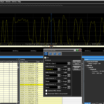
FRS compliance test instrumentation systems simulate a “power loss event” for the device under test (DUT) to initiate the FRS sequence. The test system continuously monitors the flow of power through VBUS and captures the message timing and power sequencing to ensure they meet the FRS requirements. There are specific test instrumentation and fixtures available for FRS compliance testing.
Biphase Mark Code PHY Integrity testing
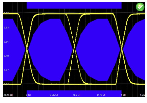
The USB PD protocol uses biphase mark code (BMC) encoding on the CC communications interface to exchange the power profiles between two USB Type-C interfaces. Confirmation of the specified power negotiation on the CC link of a USB Type-C interface at frequencies of 270 kbps and 330 kbps and verification of the quality of the power supply on VBUS is another aspect of USB PD compliance testing.
Communication of the BMC signal specified in the USB PD standard is necessary to guarantee interoperability between USB components and devices and avoid any damage due to overvoltage and current. BMC PHY signaling is tested using compliance masks. Separate mask profiles are used to evaluate the modulated signal sequences of logic “one” and “zero”.
Each manufacturer needs to apply to the USB Implementers Forum to get XIDs for its products. The initiator reads its responders’ XIDs along with other electronic certification data during the USB Type-C Authentication process. An external database (white list) that includes each XID and its related compliance test status is part of the compliance infrastructure. The initiator checks the white lists to confirm that the responder’s XID is listed after being authenticated. If the XID is on the white list, the initiator can be confident that the responder has passed compliance testing.
As a result of the 40 Gbit/s speed of USB4 (and Thunderbolt 3 & 4), measurement system noise and jitter cannot be ignored. The electrical tests for USB4 emphasize the Tf/Tf and intrinsic jitter performance of the test signal source. The test is performed by calibrating the test signal using the minimum input performance defined by the receiver standards to guarantee accurate receiver sensitivity measurement.
USB testing software
Software suites are available that support USB PD electrical and protocol compliance testing to validate and debug USB power delivery provider, consumer, dual-role device, and eMaker cable. For example, automation of the bit error rate testing (BERT) can minimize the effort needed for signal calibration and maximize test reproducibility. Various USB PD electrical and protocol compliance software suites offer several features that can speed design validation:
- Conformance to the latest USB-IF USB PD specification and testing requirements
- Performance of the BMC-PHY electrical, physical layer tests
- Performance of the BMC-PROT protocol layer tests
- Performance of the BMC-POW power state tests
- Full automation of all tests needed for USB PD certification
- Support for all types of USB PD device tests, including provider, consumer, dual-role device, and the eMarker cable.
- Automatic saving of all waveforms, making them available for subsequent analysis and debugging
- Supports automation of the USB PD compliance test process, including product registration and certification approval
Automated USB PD compliance software can enable designers and test engineers to perform all needed compliance testing and debugging in real-time and reduce product development times.
Summary
As shown, designers integrating USB Type C and USB4 into their products confront several challenges to ensure interoperability and compliance. Compared with previous generations, the latest USB specifications are more demanding due to higher power and more complex power profiles, higher data transmission speeds, and more functionality in general. To address these challenges, test engineers must start with accurate and standard-compliant test instrumentation, software, and fixtures.
References
How to Test USB Power Delivery Over Type-C, Keysight Technologies
PD 3.0 ‘Fast Role Swap” Compliance Tests, Teledyne Lecroy
Power Delivery Tests, USB Implementers Forum
USB Power Delivery Electrical and Protocol Compliance Test Software, Keysight Technologies