Not all capacitors are created equal. Some are polarized, some are ultra-stable, and others have low dielectric absorption or high volumetric efficiency—all depending on the materials and other physical characteristics in the technologies used in manufacturing. Multiayer ceramic capacitors (MLCC) are divided into types or classes, based on the materials used for the dielectric.
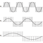
These capacitors have one parameter, in particular, that is easily overlooked but needs to be considered when choosing devices in a design; this is the “DC bias characteristic,” or the change in capacitance when a DC voltage is applied across the terminals. Clearly, supply bypassing applications place capacitors across DC voltages. Charge pumps, by their nature, also have DC voltages across their capacitors. The “flying capacitor” used to transfer charge in a charge pump, as well as the input and output capacitors, need to deal with DC voltage biasing and are therefore also susceptible to this phenomenon.
Class 1 and Class 2
The two primary types of MLCCs in use today are Class 1 (temperature compensating) and Class 2 (high dielectric constant), but there are other less common and obsolete classes as well.
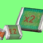
Class 1 (or Class I) capacitors use titanium dioxide (TiO2) as the dielectric material. Class 2 (or Class II) capacitors use barium titanate (BaTiO3) along with additives. Class 1 MLCCs are found in lower capacitance values and are more stable than the Class 2 capacitors. Class 1 types are usually used in applications where stability is the primary concern, such as in tuned circuits. If the EIA temperature characteristic of the capacitor starts with a C, H, L, M, N, or P (like C0G), it is a Class 1 MLCC. Class 2 MLCC capacitors have higher volumetric efficiency and other unique characteristics not found in the Class 1 MLCC capacitors. If the EIA temperature characteristic starts with an X, Y, or Z (like X7R), it’s a Class 2 MLCC.
For applications where the MLCC is being used for AC coupling or where there is little DC voltage across the capacitor, this DC bias effect will not be a factor. Since Class 2 MLCC capacitors have many attractive features like low leakage, high ripple current capacity, and small physical size, they are a preferred choice for use in charge pumps, even with this less than desirable characteristic. It was in the use of MLCC capacitors with these products that this often-overlooked parameter became apparent since the capacitor’s real capacitance directly affects performance in charge pumps.
DC bias voltage sensitivity
The DC bias phenomenon is a characteristic of all Class 2 (also called Type 2) ceramic capacitors. All manufacturers use similar materials and have similar performance, but this can vary. Careful selection of the capacitors used in a design is called for, depending on the specific application. The voltage rating, case size, temperature characteristic (Z5U, X7R, etc.), the end product’s physical size constraints, and output power level all affect the choices to optimize the design for a given application.
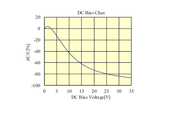
Capacitors with lower capacitance values and voltage ratings show less effect from DC bias compared to higher capacitance values in each case size and voltage rating. Most applications which use input voltages from 24-48 V can be highly affected by a capacitor’s DC bias performance. This is illustrated in Figures 1 and 2 for two relatively high capacitance and voltage rated devices.
As the voltage rating and/or capacitance values go up, the DC bias effect on a capacitor becomes more noticeable. As the case size gets smaller, the effect also becomes more pronounced. The optimal capacitance for a power supply application is highly dependent on the current that needs to be supplied. More capacitance doesn’t make the performance significantly better above some value, although the ripple voltage is improved. The following information demonstrates the trade-offs involved selecting the capacitors in a design.
Unfortunately, the DC bias performance is not always published in the capacitor’s datasheet, so it is often necessary to do some research to get the performance data. Capacitors that do not have the DC bias data available should be rigorously tested to assure acceptable performance. Also, be careful when substituting new capacitors into an existing design. Performance needs to be verified to make sure the design still works as required. Changing vendors or temperature characteristics, such as going from a Z5U to an X7R, can significantly change the DC bias performance.
MLCC voltage rating vs. capacitance
Using capacitors with a higher voltage rating than might seem to be required can offset the effect of the capacitance reduction by maintaining a higher percentage of its rated capacitance. The capacitance rating is usually specified and measured with only a small DC voltage applied, so the real capacitance will typically be much less at the rated maximum DC voltage. Capacitors will normally be selected with some voltage margin between the rating and applied voltage, but in the following cases, this is being ignored to illustrate the point.
For example, a 4.7 uF 25 V, 0805, X5R capacitor operating at 25 volts DC would actually be about 15 percent of its rated value or 0.705 uF. A 4.7 uF 50 V, 1210 X5R capacitor at 25 volts DC would be about 50 percent of its rated value or 2.35 uF. A 4.7 uF 100 V, 1210, X5R capacitor would be 70 percent of its rated value or 3.3 uF. The alternative to using a higher voltage rating is to use lower voltage capacitors in parallel, and this may be a good trade-off in some cases where the higher voltage rated part is either not available or too expensive.
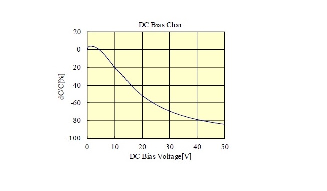
Figure 1 shows an example of DC bias on capacitance for a 22 uF, 35 V 1210 capacitor (35 V is the highest voltage 22 uF capacitor available in the 1210 case size). At 25 V, it has lost about 80 percent of its rated capacitance, so the actual capacitance is about 4.4 uF. Figure 2 shows performance for a 10 uF, 50 V, 1210 capacitor. At 25 V, it has lost a little over 60 percent of its initial capacitance, therefore, a little under 4 uF. So even though the 10 uF/50 V capacitor is rated at less than half the capacitance, at 25 V it is nearly the same capacitance as the 22 uF/35 V capacitor. But, a 22 uF capacitor is also nearly twice the cost of the 10 uF, so for the cost vs. capacitance, the 10 uF 50 V is more cost-effective.
With MLCCs, case size vs. capacitance
In capacitors, physical size does matter, since a smaller case size also affects the DC bias capacitance reduction. Looking again at the 4.7 uF, 50 V 1210 capacitor for reference, a 4.7 uF, 50 V 0805 capacitor operating at 25 V has a capacitance reduction to 0.47 uF, or less than a quarter the capacitance in a 1210 case size. This is typical of the DC bias effect on the capacitance when the case size is reduced.
MLCC capacitance values vs. case size
Finally, the capacitance value for a given case size and voltage rating makes a difference as well. A 1 uF 50 V 0805 capacitor used at 25 V will be only 0.43 uF compared to the previous 4.7 uF 50 V 0805 reduction to 0.47 uF, so the 1 uF is a little less than half the rated value, where the 4.7 uF is about a tenth the rated value. So, for a given case size there is a very pronounced effect on the true capacitance as the rated capacitance increases.