The hot wire anemometer for measuring fluid speed offers unique advantages but also has some challenging use issues.
You are undoubtedly familiar with the classic wind-speed anemometer with three cups rotating as the wind blows, while a tachometer reports the revolutions rate (Figure 1). This is a “tried and true” way to measure large-scale wind speed. In fact, measuring the velocity (speed vector) of fluids, usually but not only air, is a very common instrumentation requirement, perhaps second only to temperature(the most-commonly measured variable).
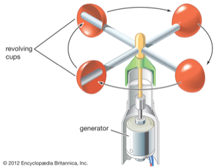
While the cup anemometer is easily understood, it’s obviously not suitable for many situations such as use in restricted pipes or even blood vessels. As a result, many other techniques and sensors have been developed to measure fluid speed, among the many options are:
- Vane or propeller anemometer; you can even buy a convenient hand-held version (Figure 2).

Fig 2: The vane anemometer uses a propeller in the flow stream and is available in many versions and models, including as a handy portable version. (Image: FLW, Inc.) - Laser Doppler anemometer, where a beam of light is divided in half, with one side going with the fluid, then recombined; the phase shift between the two beams is used to calculate the shift induced by the Doppler effect.
- Ultrasound anemometer, which measures the time of flight between an emitted pulse and its reception at the other end of the path.
- The ping-pong ball, with a ball suspended on a string, especially good for very low speeds; although simplistic and usually used for visual school demonstrations, an advanced version of this was used successfully the Phoenix Mars Lander.
There are also pressure-based anemometers such as the aircraft pitot tube, which relies on the differential pressure between a tube exposed to the moving air and one isolated from it.
Regardless of the sensor used, each of these requires some way to relate the apparent measured data to the actual speed; this can range from a modest task to a complex one. There are often calibration, compensation, and correction issues to address.
This article will look at a fluid-velocity measurement transducer called the hot wire anemometer. It has no moving parts and is very small, but is somewhat fragile and requires complex equations to relate the sensed value to the fluid speed as well as correct for inherent, unavoidable nonlinearities as well as external factors such as fluid type, ambient temperature, humidity, and angle between the flow and the sensor element.
Basic of the hot wire anemometry
The hot wire anemometer (HWA) is an electronic analog to the principle of what people refer to as wind-chill factor. In simplest terms, moving air (or fluid) cools heated objects, whether it is a person, chassis, or a heated wire. The challenge is to build a transducer, drive it, and sense it.
In more technical terms, the technique is based on the heat transfer by convection from a heated wire to the relatively cold surrounding fluid, and this heat transfer is related to the fluid velocity. Therefore, if a clear relationship between the fluid velocity and the electrical output of the system can be established, it can be used to determine that fluid velocity.
As with all electrical and mechanical measurements, one of the many issues is to ensure that the measurement sensor has minimal impact on what is being measured in a “scaled-up” version of Heisenberg’s Uncertainty Principle. (Note that fluid velocity is just the speed of fluid moving past a measurement point and is not directly related to measuring the mass flow rate, which is a function of the fluid mass and velocity. Mass flow is measured using different instrumentation, such as the Coriolis flowmeter.
The HWA principle
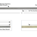
The principles of the HWA are deceptively simple and complicated at the same time. At the HWA core is the basic sensor itself: a fine wire on insulating supports (ceramic or glass, in most cases) (Figure 3) and (Figure 4). It is usually made of platinum, but other metals are also used. The wire is driven by a fixed or constant- current source (depending on the HWA topology) and self-heats. Moving air cools this self-heating by convection. That’s the easy part, relatively speaking.


There are two ways to “manage” the relationship between the current in the sensor wire and temperature:
- In the constant-temperature anemometer (CTA), the resistance of the wire is measured and thus used to infer its temperature, while the current source is adjusted to maintain the wire at a constant temperature (Figure 5). This resistance measurement is accomplished by measuring the voltage across the wire, then working through a known but non-linear relationship between voltage and resistance for a given material. The amount of current needed to maintain the resistance, and thus the temperature of the wire is a measure of the flow rate of the gas.
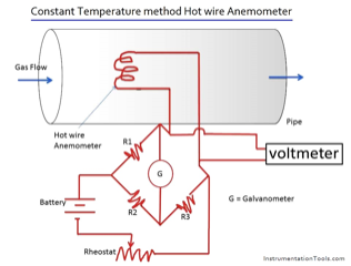
This type of measurement is somewhat similar to how the widely used RTD (resistance temperature detector) sensor is used to measure temperature. Note that the figure shows the adjustment operation as done manually, but a practical modern system would use a closed-loop analog (or perhaps digital) circuit to measure the resistance and adjust the current.
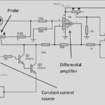
- In the constant-current anemometer (CCA) approach, the roles of the variables – resistance and temperature – are reversed, Figure 6. Here, a fixed current source is passed through the sensing element as a resistor. As this resistor cools due to the flow of gas, its resistance changes, and this value is measured, and the change in resistance can be related to the flow velocity. Again, the figure shows the use of a bridge circuit and galvanometer assess that resistance value, but in a modern circuit this would be done with a voltage sensing circuit across the resistance and a data acquisition and readout arrangement.

Part 2 will look at the structure of the theoretical relationship between flow speed, resistance, and current, as well as calibration issues. It will also look at the relative pros and cons of HWAs.
EE World References
- The working principle, applications and limitations of ultrasonic sensors
- Temperature Sensors: thermocouple vs. RTD vs. thermistor vs. semiconductor IC
- Precision-resistor devices simplify thermal sensing
- What are cryogenic temperature measurements? Part 2
- What are cryogenic temperature measurements? Part 1
- How can you get digital temperature data?
- Coriolis flowmeters, Part 2: The principle
- Coriolis flowmeters: A subtle global effect with local applications, Part 1: The challenge
- How do you calculate flow from a pressure measurement?
External References
HWA Operation and Analysis
- Science Direct, Hot wire anemometer
- Electronic Journal of Fluids Engineering, Transactions of the ASME, “Review of Hot-Wire Anemometry Techniques and the Range of their Applicability for Various Flows”
- Instrumentation Tools, “Hot Wire Anemometer Principle”
- Circuit Globe, “Hot Wire Anemometer”
- Virginia Polytechnic Institute and State University “Hot-Wire and Hot-Film Anemometry”
- University of Leicester, “Hot-wire anemometer calibration”
- Journal of Physics, “Calibration method for a hot wire anemometer”
- Middle East Technical University (METU) OpenCourseWare, “Hot Wire Measurements“
- Wikipedia, “Anemometer”
- Budapest University of Technology and Economics, “Hot-Wire Anemometry”
- Electronic Journal of Fluids Engineering, Transactions of the ASME, “Review of Hot-Wire Anemometry Techniques and the Range of their Applicability for Various Flows”
- Jove, “Hot Wire Anemometry”
- University of Cambridge, “Hot-Wire Anemometers”
- com, “Hot Wire Anemometer”
- University of Virginia, “How to use the Dantec hotwire anemometer”
- Advanced Thermal Solutions, “Understanding Hot-Wire Anemometry”
HWA History
- Annual Review of Fluid Mechanics, “Hot Wire Anemometry”
- Frederick Delbridge Knoblock, “Investigations of the Application of the Hot Wire Anemometer for Turbulence Measurements” (Caltech 1939)
MEMS-based HWAs
- Journal of Physics, “A novel design and analysis of a MEMS ceramic hot-wire anemometer for high temperature applications” (2006)
- Conference: Design, Automation, and Test in Europe, “Hot Wire Anemometric MEMS Sensor for Water Flow Monitoring” (2008)
- Micromachines, “Micromachined Thermal Flow Sensors—A Review” (2012)
- Griffith University, “MEMS Anemometer” (2007)

