There’s a confusing variety of ways to quantify power consumption. Make sure you understand what your favorite power metric means.
To most engineers, the concept of power quality pertains to characteristics of the ac line feeding grid energy to equipment in a facility. But variations of the “power quality” term now can refer not just to the ac line but also to properties of devices connected to the ac mains. Thus it may be useful to review the basics of power quality and some of its newer interpretations.
First consider an “ideal” three-phase power system. Here the current is in phase with the voltage for each phase, the phase voltage and currents are exactly 120° apart and all equal to each other, the voltage and current sine waves are not distorted the source impedance is zero, so events at the load don’t affect the source voltage, and the actual frequency is equal to the nominal frequency.
Of course, no real-world power system is ideal. There is an acceptable range of deviation. In the U.S. ANSI C84.1 defines the acceptable limits for service voltage and utilization voltage. Power Factor is one of the properties it defines. A power factor of one is ideal, meaning ac voltage and current sinewaves are exactly in phase with one another. Capacitive and inductive impedances tend to cause power factors less than one. Motors, solenoids and pumps typically have impedances containing inductive reactance, which vary with their mechanical load. Capacitors have impedances that are combinations of a typically small resistance and larger capacitive reactance component.
Reactance present in ac systems shifts the voltage and current sine waves out of phase from each other. Voltage leads current with inductive reactance and current leads voltage with capacitive reactance. Low power factor tends to arise in industrial facilities containing numerous motors or other inductive loads. Electric utilities typically charge large industrial and commercial customers a higher rate for low power factor loads.
Unbalance arises in three-phase power systems when single phase loads (lighting, office equipment, etc.) draw unequal amounts of current on each phase. This kind of load causes greater stress on the neutral conductor. Ideally loads are balanced, meaning the voltage and current phases are exactly 120° apart from each other, though the currents might not be in-phase with the voltages. A balanced three-phase four-wire wye system will have zero current on the neutral wire. The amount of current on the neutral wire in an unbalanced system rises with the unbalance, potentially causing overheating and a risk of fire.
Motors driven by unbalanced voltages generate a phenomena known as counter-torque where a small motor torque works in the opposite direction from the motor rotation. Thus part of the energy delivered to the motor works against itself.
Harmonics are a form of waveform distortion arising in circuits containing non-linear loads primarily characterized by switching power supplies. These non-linear loads may impose higher frequency sine waves on the ac input, causing a power lose in the form of wasted heat. The excess heat produced by harmonics can be detrimental to a power system. Transformers are especially susceptible to damage caused by harmonic eddy currents which circulate in the iron core and produce excess heat.
Harmonics are multiples of the main frequency, 60 Hz in the U.S. For example, the third harmonic in a 60 Hz system is 180 Hz and the fifth harmonic is 300 Hz. Power quality meters can display the magnitude of each harmonic frequency. They may also read out total harmonic distortion (THD) and total demand distortion (TDD) to provide a single harmonic distortion measurement rather than an entire spectrum.
PQR
The widespread use of power quality metrics has given rise to more specialized but similar measurements often aimed at individual ac loads or ac-powered appliances. One
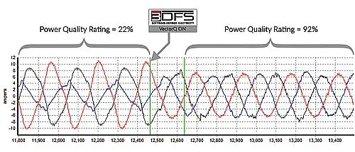
such measurement is the power quality rating or PQR, a metric created by N.C.-based engineering firm 3DFS. An electrical network with a PQR of 28% utilizes 28% of the energy consumed as electricity and the remaining 72% as heat or vibration somewhere in the electrical network.
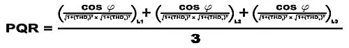
3DFS defines its PQR metric for each of the three phases and factors in both THD and phase lag/lead (cos ℘) between voltage and current.
In a nutshell, 3DFS claims ordinary power quality measurements are incomplete because they typically are calculated by some combination of harmonic distortion and reactive power. The problem, says 3DFS, is that this measurement typically doesn’t consider whether there are imbalances across phases. PQR is meant to be a more informing metric that includes such conditions. The point of this exercise is to correct for harmonics and reactive power while simultaneously balancing the phases as power flows in real time. This is something 3DFS claims it can do via something it calls a software-defined power controller.
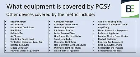
Though any device can theoretically get PQS, Bijou is targeting smaller power-consuming devices, enforcing a 2.4 kW or 2.4 kVA upper limit.
To complicate matters somewhat, there is a similar sounding metric called a power quality score, PQS. This one comes from Bijou Electronics in New York. Rather than being a metric for power consumption in a facility, PQS is aimed at individual power consuming appliances. Bijou sees PQS as potentially an energy efficiency benchmark for any device that gets plugged into the power grid. PQS is a combined metric containing power factor, efficiency or efficacy, and THD. PQS is a single number rating of power quality at each device setting or at several load settings, typically 0, 0.1, 10, 25,50, 75, and 100% load for a power supply or power adapter. Bijou has published PQS results for a number of consumer devices and typically gives results at three points, idle, average, and max PQS. Bijou defines PQS as having a value from 0 to 200—it says the reason for going to 200 rather than something smaller is to provide more detail when comparing products. This helps find differences between various power consuming devices of similar types which may bunch up if made with the same basic topology.
Though any device can theoretically get PQS, Bijou is targeting smaller power-consuming devices, enforcing a 2.4 kW or 2.4 kVA upper limit. Bijou tests consumer devices and assigns a PQS score and publishes the results online. As of this writing, the firm has published results for products that include various light bulb technologies, fans, power adapters, transformers, humidifiers, power supply modules, display monitors, and even an electric blanket.