The proving ring implements a simple principle of physics to provide precise and tangible indication of applied weight ranging up to hundreds of thousands of pounds
Part 1 of this article looked at the basic problem of calibrating sensor-based data acquisition and especially the problem of calibration of weight and force. This part looks at the factors which inspired the proving ring along with its present-day use.
As with so many technological advances, the developers of the proving ring did not start with the goal of developing a replacement for deadweight calibration. Herbert Lucius Whittemore, head of the NBS Engineering Mechanics Section, and Serge Nicolas Petrenko, an engineer in the section, were trying to resolve inconsistencies in the results of the Brinell hardness test, where a pressure gauge pushes a plunger with a ball tip at a known force into the sample under test. The diameter of the resultant indentation, which is much easier to measure accurately than its depth, is a quantitative indication of the sample’s hardness.
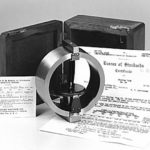
Whittemore and Petrenko found that their Brinell results were inconsistent, largely due to problems with the accuracy of pressure gauge and hydraulic pump used to impress the plunger. Using deadweights gave much better results but was impractical, especially at non-NBS locations. They came up with the idea of adopting the deflection of rings under load (Figure 1) and submitted a patent for their proving ring, number 1648375, to the United States Patent Office on September 14, 1926. It was granted on November 8, 1927.
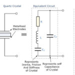
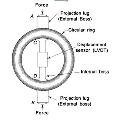
The principle behind the ring’s deflection is well known to mechanical engineers (Figure 2 and Figure 3). In simplest form, for a thin ring under modest compression (or tension) of load P, the decrease (or increase) in ring diameter is proportional to PD3/EI, where D is the diameter of the ring, E is the modulus of elasticity of the ring’s material, and I is the dependent on the ring’s cross-section.
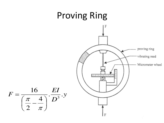
Thus, for small loads, the deflection is linearly related to the applied load. A more-detailed analysis provides a much more complicated and precise equation which takes into account various second-order factors (Reference 1), but the linear relationship remains valid. Typical deflection of a proving ring under full-scale load is just a few millimeters, and that can be measured with great accuracy and precision using micrometers and other gauges (of course, temperature plays a role in the final accuracy, but that can be controlled or factored into the calibration and compensation (Reference 2).
As with most instrumentation, squeezing that last bit of precision performance requires care in design and fabrication, even if the underlying principle is simple. Construction of a proving ring starts with an annealed, forged ring made of special steel alloys, which is then precision-ground to final size. The threaded attachment bosses which connect to ring to the rest of the system are not welded on, as this would introduce uneven stresses and subsequent errors; instead, they are part of the original forged shape although they complicate the forging. (There are slight differences in the design of these attachment points with proving rings intended for solely for compression use versus those only for tension.)
Since proving rings are operate with relatively small deflection to stay within their linear range, measuring the minuscule deflection of the ring – which is typically between 0.05 (1.25 mm) to 0.10 inch (2.5 mm) under full load for a medium-size unit – requires a unique, non-obvious approach. It is done using a vibrating reed mounted within the ring on a special micrometer screw mechanism and a small button opposite the free end of the reed. The reed is manually or electrically tapped to start it vibrating; as the ring deflects, the micrometer is adjusted until the reed’s tip grazes the button, and so the reed’s sound changes dramatically; then the micrometer position is read. Though this technique may seem almost archaic, it provides repeatable and consistent indications – the hallmarks of good metrology – with accuracy to about 0.00005 inch. Newer proving ring systems also use a carefully positioned video camera and image-measurement software to measure the ring’s deflected size.
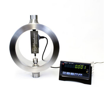
Proving rings do not drift or change with age as long as they are not used beyond their deflection limits, and many have been in use for decades. For highest accuracy, a proving ring needs to be used at a specific temperature, or a correction factor must be applied since all metals have a temperature coefficient of expansion, which affects their size. NIST or in-house deadweights can calibrate a proving ring and then used in the field at other locations, solving the on-site weight/force calibration challenge. Many new proving rings are equipped with electronic LVDTs rather than mechanical micrometers for displacement measurement and digital readouts, and older proving rings can be upgraded to digital readouts (Figure 4).
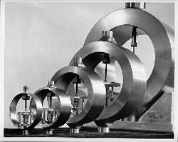
When used properly, a proving ring provides absolute accuracy of between 0.0125% and 0.075% of reading, according to Morehouse Instrument Company, Inc., the leading supplier of this precise secondary standard. A ring rated for 1000 pounds measures from 6 to 12 inches in diameter, is about 1-inch thick and 2-inches deep, weighs under 10 pounds and sells for under $5000; one with a 300,0000-pound rating is under 20 inches in diameter, weighs only about 150 pounds, and costs about $20,000, all of which are far less than their deadweight equivalents (Figure 5). As an added benefit, multiple smaller proving rings can be used in parallel to reach higher ranges, if needed.
Conclusion
Simulation and replication of key physical standards is an ongoing challenge spanning accuracy, precision, dynamic range, and other factors. Innovations such as the proving ring demonstrate, once again, that the impetus for advances in one application – here, the Brinell hardness test – is often the driver for innovation in other areas as well.
EE World References
- High Capacity Reaction Torquemeters Carry NIST Calibration
- Load Cell Designed to be Hermetically Encapsulated
- Subminiature Compression Load Cells Offer Reliability and Space Efficiency
- Stress & Strain, Part 2: Implications for electronics
- Stress & Strain, Part 1: Fundamental principles
External References
- “Proving Rings for Calibrating Testing Machines,” Bruce R. Wilson, Douglas R. Tate, and George Borkowski, National Bureau of Standards, 1946, page 216
- “Temperature Coefficients for Proving Rings,” Bruce R. Wilson, Douglas R. Tate, and George Borkowski, National Bureau of Standards, 1946, page 207
- NIST, “Calibration of the Proving Ring”
- Morehouse Instrument Company, Inc.
- “World in the balance: the historic quest for an absolute system of measurement,” Robert P. Crease, W.W. Norton, 2011.
- NIST, S. Patent 1648375
- Slideplayer, “Measurement of Force, Torque, and Pressure”
- NIST, “The Proving Ring Design”
- Hareeshna Gowda, “Unit 6: Force, Pressure, and Torque Measurement”
- NIST, “For All Times, For All Peoples: How Replacing the Kilogram Empowers Industry”
- NIST, “A Turning Point for Humanity: Redefining the World’s Measurement System”
- NIST, “Toward the SI System Based on Fundamental Constants: Weighing the Electron”
- NIST, “Universe’s Constants Now Known with Sufficient Certainty to Completely Redefine the International System of Units”