Examine the low-frequency signal source in many kinds of test equipment and you are likely to find a harmonic oscillator. A harmonic oscillator typically consists of an amplifier that gets its input from its own output. A part of the output feeds back to input while the rest is an output signal. To support oscillations, the phase shift caused by the amplifier and feedback network must be zero. This criterion is unfulfilled at all but one frequency.
Modern test equipment is more likely to use a relaxation oscillator rather than a harmonic oscillator. A relaxation oscillator typically has one or more voltages or currents that change suddenly during each cycle of the oscillation. For example, an astable multivibrator is a relaxation oscillator.
 That brings us to the function generator, which typically is based on a voltage-controlled squarewave oscillator producing a suarewave signal. Here, an integrator produces a triangular waveform from the square wave, and a sinewave-shaping circuit produces a sinusoidal waveform from the triangular waveform. The sinewave shaping circuit only approximates a true sineusoid, so there is a distortion of around 1.5%.
Returning to the harmonic oscillator, not all harmonic oscillators are electronic circuits. Examples of harmonic oscillators include chemical reactions, pendulums, physical bodies attached to springs, acoustical systems, and ocean waves. The simple definition of a harmonic oscillator is a system that has an equilibrium position where, when displaced from this position, a restoring force F proportional to the displacement x arises, in accordance with
F = -kx where k is a positive constant.
Harmonic oscillators can be categorized as either driven and damped. In damped harmonic oscillators, a damping force — typically frictional or electrical — applied to the oscillator causes it to be overdamped or underdamped. If it is overdamped, it will eventually stop oscillating, returning to its equilibrium state. An example is a swinging pendulum that is not powered after the initial impetus. The damping mechanism is primarily air friction. If the harmonic oscillator is underdamped, it will oscillate at a lower frequency than in the undamped state as the amplitude decreases.
If external force is applied to the harmonic oscillator, it is known as a driven oscillator. An example is a pendulum clock powered by hanging weight that is raised periodically, or by a coil spring that is rewound as needed.

Block diagram of a harmonic feedback oscillator. A portion of the amplifier output is fed back through a feedback network to the amplifier input. When powered up, circuit noise initiates oscillation. The signal is filtered to create a sine wave at the design frequency which is amplified to provide a stable output.
If a harmonic oscillator is neither driven nor damped, it is known as a simple harmonic oscillator. This variety of oscillator exhibits periodic, sinusoidal oscillation with unchanging amplitude. It is strictly an ideal device because in the real world there is some amount of friction or gravitational effect. In terms of frequency, the period T is: = 2π/ω where ω is the angular frequency of the oscillator. Its frequency f is f = 1/T.
A feedback oscillator can be built around an operational amplifier. The feedback network varies depending upon the intended application. Resistors and capacitors comprise a simple RC network suitable for low-frequency audio tones. Two subtypes are the phase-shift oscillator and the Wien bridge oscillator. The phase-shift oscillator is a linear device that creates a sine-wave output, which is fed back to the input through resistors and capacitors in a ladder network, shifting the phase 180° at the oscillation frequency. The amount of phase shift rises with frequency. A common configuration consists of three identical resistor-capacitor stages for a phase shift of 0° at low frequencies to 270° at higher frequencies. The inverting amplifier is typically an op amp, bipolar junction transistor (BJT) or a field-effect transistor (FET).
An LC harmonic oscillator is tuned by a tank circuit or resonator, which consists of a capacitor and inductor configured to store and release electrical energy to produce a stable sine wave at radio frequencies. LC oscillator implementations are Hartley, Colpitts and Clapp circuits.

A Hartley oscillator built around an op amp. The original, invented by Ralph Hartley in 1915, was based on a triode vacuum tube.
The Hartley oscillator is an amplifier in conjunction with a tuned circuit having a single capacitor in parallel with two series inductors, or a single tapped inductor. The feedback signal used to obtain oscillation is derived from the center connection of the two conductors.
Another LC oscillator is the Colpitts circuit. Rather than two inductors and one capacitor as in the Hartley circuit, the Colpitts oscillator has two capacitors in series across the inductor. (Both resonant circuits are voltage dividers, invented three years apart.)

Colpitts Harmonic Oscillator, invented by Edwin Colpitts in 1918.
James Clapp is credited with inventing the Clapp oscillator in 1948, although the circuit had been in operation at the BBC ten years earlier. The three capacitors form a voltage divider that determines the amount of feedback voltage applied to the transistor input. The addition of a third capacitor makes the Clapp harmonic oscillator as much as 400 times more stable than the Colpitts oscillator, and therefore more suitable for precision applications. It can be used as a variable frequency oscillator by making V0 a variable capacitor. The sine wave output frequency f0 is given by
 where C is the total capacitance in the tank circuit,

A problem arises in using the Clapp oscillator as a variable frequency oscillator. It works only over narrow bands because the loop gain varies as 1/f3, so all but a narrow range will overdrive the amplifier.
Crystal oscillators are built around the same circuits as LC oscillators, with piezoelectric crystals, usually quartz, replacing the resonant circuits. A piezoelectric crystal vibrates mechanically, serving as the resonator. The frequency of mechanical resonance sets the resonant frequency. These inexpensive crystals are ground to precise dimensions that determine the frequency, and terminals with leads or pins are attached so plug-in crystals can generate separate frequencies for amateur transmitter gear.
 In conjunction with quartz crystal resonators, the Pierce oscillator circuit is frequently used, particularly for IC clock oscillators. It is inexpensive to manufacture, accurate and highly reliable due to the few components required – one resistor two capacitors and the quartz crystal.
One-port devices, with two terminals that have negative resistance, can be used as amplifiers in linear oscillators. The apparent contradiction in “negative resistance” is quickly resolved when it is realized that to work, a dc bias voltage must be applied. Negative-resistance devices include Gunn diodes, magnetron tubes, tunnel diodes and IMPATT (Impact Avalanche ionization Transit Time) diodes. High-frequency oscillators generally incorporate negative resistance to counteract inevitable capacitive losses.
Sawtooth, square and triangle waveforms, as well as other nonlinear outputs, are best generated by relaxation generators. They consist of energy-storing capacitors or in some applications the more expensive inductors. A nonlinear switching device such as a latch, Schmitt trigger or negative-resistance component comprises the feedback loop. A switching device causes abrupt changes in the waveform.
Multivibrators consist of two amplifiers, transistors, vacuum tubes or mechanical devices, with coupling components such as resistors and capacitors. An astable multivibrator is unstable in both states. Since it continually switches from one to the other, it qualifies as a relaxation oscillator.
A variation is the one-shot, or monostable multivibrator. One state is stable and the other state is not. An external pulse causes the device to enter the astable state, where it remains for a predetermined time interval, after which it returns to the stable state.
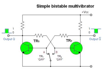 A bistable multivibrator is stable in either of its two states, switching between them in response to external pulses. It is, accordingly, known as a flip-flop, very widely used to store single bits of information.
A bistable multivibrator is economical and suitable for massive integration because the resistive or capacitive network can be replaced by direct coupling. Due to the absence of capacitors, there is no charge or discharge time. Switching can be accomplished by means of set and reset terminals. The flip-flop therefore functions as the basic storage element in sequential logic.


Leave a Reply
You must be logged in to post a comment.