Organizations that test power circuits for safety have specific definitions of working voltage and other parameters that bear heavily on how products get safety certifications permitting their sale.
Dylan Howes, MINMAX Power, Inc.
Safety approval agencies have been evaluating both industrial and consumer products for well over a century. The need for approval by such agencies has risen rapidly since the early 1920s. Today it would be impossible to bring a product to mass market without first obtaining the industry standard safety approvals.
For product design engineers, it is critical to consider the implications of applicable safety approval standards early in the design process. This means understanding the safety approvals granted to components and subsystems. Navigating safety approval requirements can be cumbersome, and there are some common misconceptions associated with the standards that govern dc-dc power converters. Of particular importance are working voltages and how they affect some of the parameters to which safety standards apply.
Approval agencies such as the Underwriters Laboratory (UL) and the Technischer Überwachungs-Verein (TUV) grant certifications of compliance to products against safety standards specified by the International Electrotechnical Commission (IEC) and/or the International Organization for Standardization (ISO). Variations do exist between the conditions of compliance from agency to agency for a single given standard, depending primarily on the geographical region in which the agency operates and the applicable legislation within that region. It is for this reason that compliance declarations are often given as the IEC or ISO standard number, prefixed with an abbreviation that indicates the region for which the standard has been approved i.e. EN60960-1 (EN stands for European Norm).
DC-DC power converters are typically evaluated against IEC60950-1, the Standard for Safety of Information Technology Equipment (ITE), but can also be evaluated against additional, more specialized standards depending on the market of the end product. One such specialized standard is the standard for Safety of Medical Electrical Equipment, or IEC60601-1. This standard specifies much higher degrees of isolation than IEC60950-1. It does so to protect patients who may be in continuous or temporary physical contact with an electrical device that is fed from a hazardous voltage source such as a 120-V or 230-V ac wall outlet.
Importance of isolation
Many relevant safety standards specify criteria for a circuit to be considered an Extra-Low-Voltage (ELV) circuit. This designation indicates that the potential differences between conductors within the circuit do not exceed a certain value. This value may differ between standards but is typically around 42 Vac or 60 Vdc. These lower voltages greatly reduce the risk of electric shock.
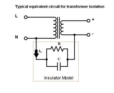
Transformers can provide isolation between two sides of a circuit, but there is still a potential connection between the two sides. One way to model the connection is with an RC network. Both R and C have extremely high values.
There are three commonly referred to types of ELVs. A Functional ELV (FELV) typically gets its ELV status via a semiconductor device such as a linear regulator and does not necessarily have any galvanic isolation from higher voltage, hazardous circuits, or from earth ground. FELV is the least stringent of the three ELV designations.
A Protective ELV (PELV) must have a galvanic isolation from any non-ELV circuit and must not become continuous with those higher voltage circuits via any single fault, apart from an earth ground fault. This means PELV circuits may contain a direct connection to protective earth ground.
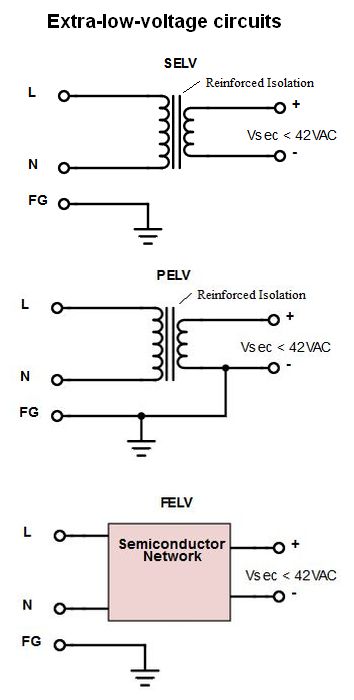 The most stringent ELV designation is the Safety ELV (SELV). Some standards refer to an SELV as a Separated ELV rather than a Safety ELV. An SELV is an ELV which cannot under any single fault condition become continuous with any non ELV circuit or with protective earth ground, such that even in the event of an earth ground fault, the ELV is maintained. SELVs are typically obtained through use of reinforced insulation.
One major focus of most electrical safety standards is the isolation barrier between hazardous voltages (greater than approximately 42 Vac or 60 Vdc) and these SELV circuits. End-products must be designed such that a user cannot touch hazardous high voltages. In an isolated power supply, the input terminals are not electrically connected to the output terminals. Rather, energy transfers from the primary side of the converter to the secondary side via the magnetic field within a transformer. This electrical isolation will allow the secondary side of the converter to be classified as an SELV even if the primary side has an electrical connection to a hazardous voltage, under the condition that the isolation barrier can prevent arcing or tracking that would render the primary and secondary sides continuous.
Accordingly, both IEC60950-1 and IEC60601-1 specify tests, along with pass/fail criteria, that determine a product’s ability to keep high voltages away from the SELV circuits that may reasonably touch users during normal operation, or during single fault conditions. The standards also specify acceptable levels of leakage current, the mains current that flows through the isolation barrier during standard operation of the device.
Defining working voltage
Working voltage is a parameter that can be used to describe and qualify the standard operating voltages that a system or sub-system can or will see during normal use. In general, the working voltage of a given device is the highest voltage to which that device can be subjected continuously without beginning the process of dielectric breakdown, or otherwise sustaining damage.
We can also describe an electrical system’s working voltage as the highest voltage present within that system during normal operation. That is, any electrical device that gets its power from a standard ac wall outlet in North America could be said to have a working voltage of 120 Vac.
Conversely, we might describe an electrolytic capacitor somewhere within the device, downstream of a dc switching regulator, to have a working voltage of 25 V, the highest rated voltage that that the capacitors dielectric material can withstand without breaking down. Safety standards utilize working voltage ratings to determine requirements on other parameters such as dielectric strength and creepage distance.
Dielectric materials used for electrical insulation have large nominal electrical resistivities, typically on the order of tens or hundreds of tera-ohm-meters. These nominal resistivities, however, are ultimately a function of the electric field strength within the material – there is an electric field strength for which the dielectric material will experience a sudden and drastic drop in resistivity. Such an event will allow current to flow relatively unimpeded through the material.
This phenomenon is known as dielectric breakdown. If an insulation barrier between a hazardous-voltage circuit and an SELV circuit breaks down, harmful currents can flow into the SELV circuit, posing serious health risks to anybody touching it. For this reason, safety standards specify requirements on the dielectric strength of the insulators that create these barriers. These requirements are verified during the safety agency approval process via a dielectric strength test, commonly known as a Hi-Pot (High Potential) test.
An insulating material’s rated working voltage is used, in part, to determine the Hi-Pot test voltage and duration according to tables given in the safety standards. A particular standard should be referenced to determine exact Hi-Pot test values for a given insulation. But a useful rule of thumb is to assume a Hi-Pot test voltage of at least 1 kV greater than twice the rated working voltage as given in equation [1]:
![]()
where VHi-Pot = Hi-Pot test voltage, Vw = rated working voltage. In reality, standards typically specify a somewhat less linear, and frequently more stringent, working-voltage-to-dielectric-strength relationship. Recall that dielectric breakdown results from an excessive electric field strength. Electric field strength is a function of both the potential difference between two conductors and the distance between them as given in equation [2]:
![]()
where d is the distance in meters between the conductors. Accordingly, it is not the resistivity of the dielectric material alone that determines its ability to separate a hazardous voltage circuit from an SELV circuit. The physical separation of the conductors and the thickness of the dielectric also factors in. It is for this reason that safety standards mandate minimum distances between the conductors of a hazardous voltage circuit, and an SELV circuit. These separation distances are known commonly as creepage and clearance distances.
Creepage is the shortest distance between two conductors as measured across the surface of a dielectric material. Clearance is the shortest distance between two conductors as measured through air.
A circuit’s nominal working voltage is used, in part, to determine these minimum spacing requirements. Other factors that are considered when determining minimum spacing requirements are the environment (i.e. the likelihood that conductive pollution will accumulate across the surface of an insulator) and the overvoltage category of the circuit (the likelihood of occurrence, and magnitude of transient voltages).
Leakage current is another parameter that is important for evaluating an isolation barrier between a hazardous-voltage circuit and an SELV circuit. Two different values of leakage current are typically specified and evaluated during the safety approval process: earth leakage current and touch current.
Earth leakage current is not typically an important parameter for dc-dc converters as they are downstream of the main ac-dc converter, and they are not frequently connected to earth ground. Touch current is a maximum measure of how much current flows from the primary side of a dc-dc converter to the secondary side at the insulator’s rated working voltage.
A real insulator can be modeled as a resistor and a capacitor in parallel. The value of resistance R is determined by the insulator resistivity and physical size according to equation [3]:
![]()
where ρ is the dielectric resistivity, l is the thickness of the dielectric along the shortest path between the two conductors of interest, in meters, and A is the cross-sectional surface area of the insulator, in meters-squared. The value of the capacitor C in the model is determined by the material’s relative permittivity according to equation [4]:
![]()
where εr is the material’s relative electric permittivity, ε0 is the permittivity of free space, and A and l are as defined above. Using the equations [3] and [4], along with Ohm’s law, it can be shown that the current flowing through the complex impedance of an insulator between two isolated circuits can be described in terms of its working voltage and material properties as given in equation [5]:
![]()
where IL is the leakage current in Amperes, Vw is the rated working voltage, j is the square root of (-1), f is the frequency of voltage, and the other parameters are defined as above. In examining equation [5], one can observe that leakage currents are mitigated by insulators with large resistivities and by longer creepage distances. Conversely, leakage currents are worsened by higher relative electric permittivity, larger cross-sectional surface areas, voltages at higher frequencies, and of course, higher working voltages.
Note that in the case of dc-dc regulators, f is zero. The second term in the numerator can be omitted leaving only a few material parameters of interest.
The bottom line for leakage current is that higher system working voltages call for well-designed insulation barriers capable of keeping hazardous currents out of SELV circuits during normal operation. When designing a piece of equipment that will go through a safety approval process, designers must consider how the system working voltage and the rated working voltages of insulating materials affect the parameters that safety standards will test. A good first step is to select a dc-dc converter that meets and/or exceeds the dielectric strength, creepage, clearance, and leakage current requirements associated with the product’s working voltage.
Though dc-dc converters are often used to convert relatively low voltages on the primary side, these seemingly low voltages may be galvanically connected to circuits at hazardous voltages in practical applications such as motor control systems or other offline designs. Use of a dc-dc converter with a high working voltage rating readily allows the secondary side of the converter to be considered a SELV circuit, regardless of any galvanic high voltage connections upstream in the system.


Leave a Reply
You must be logged in to post a comment.