The conceptually simple idea to determine current by measuring voltage across a known resistor shows the subtle nature of design tradeoffs.
There’s probably no phrase that misrepresents the realities of engineering design other than “hey, that should be no big deal.” Even simple-looking design decisions are often not so simple. The reality is that a large part of engineering design is managing the tradeoffs among many performance, cost, and manufacturability constraints. The designer must try to quantity and answer questions such as “how much is that feature worth here?” and “what and how much of this are we willing to give up to get more (or less) of that?”
It can be challenging to provide a crisp example of such a tradeoff dilemma. Fortunately, there is one widely used and highly illustrative case: sizing the current-sense resistor widely used to measure current going into a load or to/from a battery. It’s a near-perfect example of how the answer to a well-defined question means deciding on an optimum value based on two basic equations and aided by design judgment, and with no single “right” answer.
It begins with V = IR
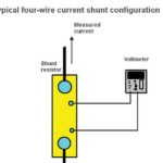
It’s necessary to measure current flow to a load or into and out of a battery in many designs. There are several ways to do this, and among the most widely used is via a sense resistor. The idea is simple: insert a resistor of known value in series with the current-carrying lead, measure the voltage drop across it, do the simple I = V/R math (which can be done digitally but is often accomplished with an analog circuit), and you’re done (Figure 1). (Note: this in-line series resistor is often called a “shunt” resistor which is a misnomer, as a true shunt is in parallel with a load.)
This sensing solution seems fairly straightforward, and it is – in theory. But engineering design is where principle meets reality and where the balancing decisions are made. The obvious question here is what value of resistance to use for that resistor, and that’s where the tradeoffs begin:
- On one side, a larger resistor makes the voltage reading easier and provides higher resolution as it increases the dynamic range and improves signal/noise ratio (SNR) of the voltage reading.
- However, that larger-value resistor also “robs” the load of available rail voltage, as the drop subtracts from the power-rail voltage to the load. Therefore, a smaller resistor is better in terms of minimizing loss of available voltage to the load.
Some basic math shows the dilemma. Consider a 5-V rail delivering a modest 2-A maximum to the load, both reasonable mid-range values. A 100-mΩ resistor will produce a maximum 200-mV drop, and that is not a large value to work with when you are trying to measure current to, say, 1% (here, 2 mV) in the presence of noise and other circuit issues. Also, that 200 mV drop represents 200 mV/5V = 0.04 or 4% of the rail, which is a lot to “give away.”
Further, a resistor in the output loop from source through load to ground (or circuit common) can compromise the loop dynamics and transient response. The source and its controller see that resistor as part of its load, but it is not part of the real load the source is trying to supply (designated “Load” in Figure 1). There’s a mismatch between what the source perceives as its load and the true load, which can impact the anticipated versus real performance. Any power dissipated by the resistor (P = I2R) adds to system inefficiency as well.
So the sense-resistor dilemma is clear: a higher resistance value results in a larger voltage drop (good for measuring) but also “steals” more of the rail’s maximum voltage that can be delivered to the load, adversely affects output-loop dynamics and decreases efficiency (all bad).
What’s a “rule of thumb” starting point for how much voltage drop should be acceptable and the corresponding resistance value? It turns out that across a wide range of situations ranging from low-voltage/low current designs to much higher ones, a 100-mV drop seems to be a good starting point. Given this voltage drop and the maximum current, it’s straightforward to calculate the correct resistance value.
What resistor values are commonly used for current sensing? It may be a surprise for designers who are used to selecting resistors of 1, 10, or even 100 kilohms. Do the math, and you’ll see that resistors are usually below one ohm and often go well below that value into the single-digit milliohm range and even lower. These “oddball” values are so widely used that they are standard components available in many configurations and ratings from multiple vendors.
There’s more to the story than just picking a resistor with a low value, as the impact on reading resolution, SNR, and wasted rail voltage is just one aspect of the problem. The other consideration is also important but somewhat more difficult to assess: the effect of self-heating on the sense resistor value due to temperature coefficient and resultant drift. That’s the subject of Part 2 of this article.
EEWorld Related Content
Current sense chips comes in 0603 and 0805 sizes
5-W surface-mount current sense shunt runs cool at high power levels
Power shunt current sense resistor dissipates 12 W
Current sense resistors for power supply and motor drive designs feature values down to 200μΩ
High Power Current Sense Resistor Offers Compact Solution
References
Riedon, “Understanding Resistors and Temperature
Vishay/Dale, “Temperature Coefficient of Resistance for Current Sensing
Vishay Dale, “Change Of Resistance Due To TCR Calculator
Vishay, “Shunts, Current Shunts, and Current-Sensing Resistors
Bourns, “Using Current Sense Resistors for Accurate Current Measurement\
Caddock, “Non-inductive Current Sense Resistors”