The problem with even a high-end electronic oscillator–such as a quartz crystal oscillator, dielectric resonator, sapphire resonator or air dielectric resonator–is that as the output frequency rises, excessive phase noise also rises. Optoelectronic oscillators are not subject to this and other dysfunctional high-frequency characteristics, and consequently they are suitable in certain exacting 21st century applications including radar, aerospace engineering and 5G wireless communications links. These demanding applications require oscillators having high spectral purity, which can only be achieved by implementing optical components.
Optoelectronic oscillators are based on the output of a continuous-wave laser connected to a modulator. This light energy is fed first to a specific length of optical fiber functioning as a delay line. The resulting signal resonates at a frequency determined by the wave guide length. Next, the resulting oscillating signal passes into a photodiode, amplifier and electronic bandpass filter, then to an intensity modulator. The ensemble forms the optoelectronic cavity. As long as the gain here is greater than the loss, an oscillating signal is maintained.
By definition, the output of an optoelectronic oscillator can be either optical or electronic. Spectral purity is achieved by exceptionally low loss in the optical fiber delay line so the optical cavity has a high Q which, as a metric, is equal to the stored energy in the cavity divided by the loss there, which is minimal because this energy consists of photons rather than electrons.
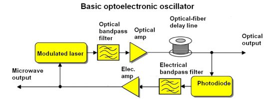
Basic OEO block diagram. In versions of this oscillator fabricated on ICs, the fiber-optic delay line is typically replaced with an atomic vapor cell.
Like any oscillator, optoelectronic oscillators generate and maintain a periodic output by means of a feedback loop. The feedback loop consists of the amplified output of the photodetector, a filter, a phase-shift as needed, and a connection back to the modulator. If gain exceeds loss and the circulating waves are combined in phase, the feedback loop generates self-sustaining oscillation without a degraded Q-factor. Because light traveling through the optical fiber undergoes minimal loss, spectral purity at high frequencies is maintained.
Spectral purity (no noise, no jitter) depends upon controlling losses in the feedback loop. To minimize this dissipation, high-Q optical resonators are implemented because piezoelectric quartz resonators can only operate at frequencies up to 100 MHz. And the Q-factor of a conventional electronic resonator drops at higher frequencies.
Phase noise, mitigated in the optoelectronic oscillator, is closely related to timing jitter. Phase noise consists of frequency fluctuation in single-sideband spectral power density, which is quantified in units of dBc/Hz (decibels relative to the carrier per Hertz). The pure fundamental is removed from any calculation of phase noise. The various sources of phase noise arise, in fact, at discrete frequency offsets. One example is a waveform shaped by temperature fluctuations. At the lowest frequencies, 1 – 10 Hz, these irregularities are known as flicker noise. Higher in the frequency spectrum, 10 Hz – 1 kHz, is white phase noise, and above that, phase noise in the output of an optoelectronic oscillator has a flat noise response. In digital signals, timing jitter is mostly applicable to the clock output.
Lots of research has gone into creating optoelectronic oscillators small enough to be built into a single IC. Here the electrical bandpass filter and the long optical fiber delay line simply won’t fit. But an atomic vapor cell is small enough to form the frequency-selective component in a chip. Atomic vapor cells often combine silicon wafer-based microfabrication and ultrasonic machining, or use hollow-core pyrex fibers, to produce a cavity that is charged with a particular atomic gas. The technique has been successfully used in atomic clocks.
Similarly, the fiber delay line and electrical bandpass filter have been replaced by a whispering-gallery-mode resonator. It uses the fact that energy waves can traverse a concave surface without excessive loss of amplitude. This phenomenon was observed in the Whispering Gallery of St. Paul’s Cathedral in London. As Lord Raleigh explained, acoustic energy in this configuration decays in intensity only as the inverse of the distance, not the inverse square, like sound radiating in all directions.
The phenomenon exists for light as well. The resonators are built around microspherical glass shells. Light traveling close to the edge of the sphere continuously reflects back inside the sphere by total internal reflection at the cavity-air interface and is trapped inside. If the circulating beam of light returns to the same point with the same phase, it interferes constructively with itself and forms resonant standing waves. Such small high-Q cavities within an optoelectronic oscillator permit these structures to be used in single ICs. Potential uses are in GPS instrumentation in satellites which, in addition to radical miniaturization, requires precise clock signals for GPS synchronization. In RF signals, phase noise is minimized at frequencies in excess of 35 GHz.
Another related implementation is the electro-absorption modulator, which involves an altered configuration of the intensity modulator. Most electro-absorption modulators take the form of a waveguide with electrodes for applying an electric field in a direction perpendicular to the modulated light beam. The field changes the light absorption spectrum and band gap energy. The electro-absorption modulator has a nonlinear response so optical pulses are generated within the optoelectronic cavity along with the electrical signal. Only one cavity is required and the phase noise in optical pulse and electrical signal are in sync. Multiple optical pulses streaming at different frequencies can be generated simultaneously. Eight signals, for example, can be multiplexed and conveyed from the output of the device.
The optical filter can select one of these wavelengths to oscillate in the cavity, creating a low-phase-noise RF signal, which modulates all the other wavelengths so they are in sync and have the same phase noise. The advantage in this circuitry is that it can create multiple low-phase-noise synchronized clock signals throughout a network.
Other types of modulators are useful, such as the phase modulator, which changes the phase rather than frequency or amplitude of an unmodulated optical wave. This creates an optical output of constant intensity from the phase modulator. No dc bias control is needed. Before photodetection, the phase-modulated signal must be converted to intensity modulation.
A variation is polarization modulation. Here again, the signal must be converted to intensity modulation prior to photodetection. The polarization modulator is capable of speeds in excess of 40 GHz. It can be configured with one or more frequency doublers.
In addition to functioning as low-phase-noise sources and optical pulse generators, optoelectronic oscillators can be used for clock recovery and synchronization. Injection locking is a process that can lock two oscillators so their outputs are synchronized. Around the time that James Clerk Maxwell determined that light is a form of electromagnetic radiation, Christiaan Huygens discovered that adjacent wall-mounted pendulum clocks would become synchronized. This was due to mechanical vibrations conveyed along the wall. A related phenomenon, known as injection locking, applies to multiple loops within an optoelectronic oscillator. These loops combine RF signals to form a single low-phase-noise signal that has many applications, including clock recovery from degraded signals.
The optoelectronic oscillator has been modified so as to open up numerous new signal processing applications. One example is the millimeter-wave optoelectronic oscillator. A simple method has been to employ higher frequency devices, typically operating at 39 GHz, by using a polymer modulator, achieving a phase noise of -100 dBc/Hz, an improvement of 30 dB with respect to a conventional RF signal source. Two separate lasers are required, operating at different frequencies, in addition to zero-dispersion optical fiber in the dual-loop cavity. This specialized fiber is necessary at 40 GHz because otherwise the power loss would preclude oscillation.
Another way to achieve results at these high frequencies is to use frequency multiplication within the optoelectronic oscillator. In a master-slave configuration the master operates at 10 GHz and the slave at 40 GHz. When the master signal is applied to the slave, the end product is stable. Variations in this circuitry have attained over 50 GHz.
Conceptually, frequency multiplication is not overly complex. A few simple components are all that’s needed. The basic idea is that a sinusoidal signal is fed into a nonlinear circuit such as an amplifier that distorts the input signal, generating harmonics. Then, a bandpass filter selects the desired frequency, removing the fundamental and other harmonics. Often it is less costly to generate and process a lower-frequency signal. Multipliers in cascade configuration can generate microwave or millimeter outputs. The technique is effective in frequency synthesizers and communications circuits. This process works as well in the field of nonlinear optics. Lasers employ nonlinear distortion in certain crystals to generate up-spectrum harmonics.
The nonlinear circuit can be chosen to make specific desired harmonics. (A full-wave rectifier can function as a frequency doubler while a tripler can consist of an amplifier overdriven to produce a square wave.) These circuits can be cascaded to produce any whole integer frequency multiplier.
A phase-locked loop can function as a frequency synthesizer. A reference frequency is used to generate a multiple. The signal from a voltage-controlled oscillator is divided down and fed along with the reference signal to a phase comparator. Then, a converted voltage is fed to the voltage-controlled oscillator to alter the frequency. These various techniques are useful in building optoelectronic oscillators.


