Decibels, (derived from bels, old units which, like unwieldy farads, are rarely used) are convenient and user-friendly terms for expressing the ratio between two amounts of power on a logarithmic scale or the amount of change, amplification or attenuation, over time of a single amount of power.
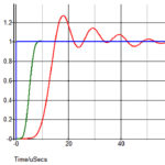
In power and sound ratios, the factor is frequently in the millions, which makes it difficult to graph the two quantities within an oscilloscope display. For this reason, modern sampling oscilloscopes offer in addition to the linear option a logarithmic scale. The ratio R of the two power quantities, by definition is:
R = 10log10 (P1/P2)
where P1 and P2 are the respective powers of the two signals. Accordingly, a signal that is twice the amplitude of another signal is roughly 6 dB relative to it because log10 2 = 0.3010. A signal that is 10 times the amplitude of another signal is 20 dB. A signal that is 1/10 the amplitude of another signal is -20 dB.
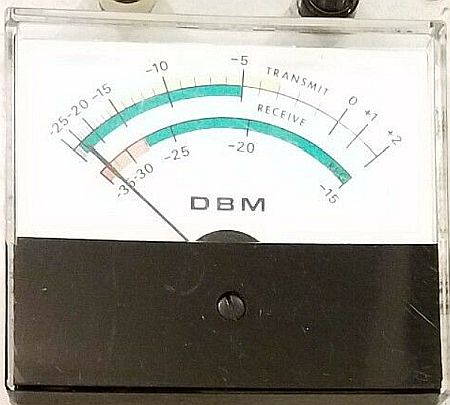
Notice that in the above cases, where decibels are used, one signal is compared to another. However, often decibels appear to be absolute measures. But always a reference quantity is required, even if it is simply implied by a letter appended to the end of the expression. For example, dBm means decibel milliwatts.
The above expression is valid for the ratio of one power level to another, but not for one current level to another, or for one voltage level to another. For voltages and currents, the ratio Rv and Ri respectively is
Rv = 20log10 (voltage/reference voltage)
Ri = 20log10 (current/reference current)
This brings up the question of why the logarithm of voltage and current ratios are multiplied by 20 instead of 10. The reason comes from the definition of the dB–it is not because a “voltage dB” or a “current dB” differs from a “power dB.” A dB is a dB. Substituting for power values using the equations P = (V2/R) and P = (I2R) makes the ratios inside the parentheses of the decibel equation become V2/Vref2 and I2/Iref2. We now use the identity log (valueExp) = Exp × log (value). In the case of the voltage and current ratios, the calculation is 10 × 2 log (ratio) = 20 log (ratio).
 Another point to note about decibels is that gains and losses of stages in a radio system can be added together if they are specified in dB. For example, an antenna with 10 dB of gain connected to a preamp with 20 dB of gain gives a total gain of 10 + 20 = 30 dB. Similarly, a power amp with 20 dB of gain connected to a feed line with 3 dB of loss and an antenna with 12 dB of gain gives a total gain of 20-3+12 = 29 dB.
One area where dB measurement units prevail is that of sound intensity or sound pressure level (SPL). The usual practice is to have the reference level of 0 dB correspond to a pressure of 0.0002 microbars, the standard threshold of hearing. SPL in the average home is about 50 dB above the 0 dB threshold. A vacuum cleaner one meter away puts out about 70 dB. The threshold of discomfort from sound intensity is 120 dB. Each 10 dB represents a factor of ten difference, so 120 dB represents a pressure 1,012 times greater than the reference threshold level. Ears respond logarithmically to changes in sound level, explaining why the decibel is a useful tool of comparison.
Decibels also arise in amateur radio. There received signal strengths on the HF bands are usually reported in S units. Each S unit represents a change in strength of 5 to 6 dB. It may be useful to consider that a change in signal strength of one S unit is a change in signal power of approximately four.
The abbreviation dB is often followed by a letter. This means the value was calculated using a specific reference value. The letter indicates the value is decibels with respect to a specific reference value. For example, when power levels are given in dBm, 0 dBm corresponds to the reference power of 1 mW; 10 dBm would be 10 times that or 10 mW. And -6 dBm would be 0.25 mW.
Consider an example where a transmitter puts out 100 W, a feed line has a 3 dB loss and an antenna has a gain of 10 dB. We convert the power to dBm, then do the additions and subtractions and convert back: 100 W = 100,000 mW = 105 mW, so the power level is +50 dBm. If we lose 3 dB in the coax, we are down to +47 dBm (+50 – 3 dB loss). Finally, we gain 10 dB at the antenna for a net result of +57 dBm. This is 7 dB above 50 dBm, so the power has gone up by more than 5x.
You can find online calculators that convert between dBm and watts, such as the one at www.radius.net/power-to-dbm-conversion.html or www.rapidtables.com/convert/power/dBm_to_Watt.html.
There are numerous dB abbreviations followed by letters. Here is a partial list of those widely used in electronics:
dBV, dB(VRMS) – voltage relative to 1 V, regardless of impedance. Used to measure microphone sensitivity.
dBμV or dBuV dB(μVRMS) – voltage relative to 1 μV. Widely used in TV and antenna amplifier specs. 60 dBμV = 0 dBmV
dB SPL (sound pressure level) – for sound in air and other gases, relative to 20 micropascals (μPa), or 2×10⁻⁵ Pa, approximately the quietest sound a human can hear.
dB SIL–dB sound intensity level – relative to 10−12 W/m2, roughly the threshold of human hearing in air.
dB SWL–dB sound power level – relative to 10−12 W.
dBA, dBB, and dBC–Symbols often used to denote the use of different weighting filters to approximate the human ear’s response to sound, although the measurement is still in dB (SPL). Other variations are dBA or dB(A).
dBFS–dB(full scale) – the amplitude of a signal compared with the maximum which a device can handle before clipping. Full-scale may be defined as the power level of a full-scale sinusoid or alternatively a full-scale square wave. A signal measured with reference to a full-scale sine-wave appears 3 dB weaker when referenced to a full-scale square wave, thus: 0 dBFS(fullscale sine wave) = −3 dBFS(fullscale square wave).
dBVU–dB volume unit
dBsm, dB(m2) – in radar, decibel relative to one square meter: measure of the radar cross section (RCS) of a target. The power reflected by the target is proportional to its RCS.
dBμV/m, dBμ–dB(μV/m) – electric field strength relative to 1 microvolt/meter. Often used to specify the signal strength of a TV broadcast at a receiving site (the signal measured at the antenna output is reported in dBμV).
Dbf, dB(fW) – power relative to 1 femtowatt.
DBW, dB(W) – power relative to 1 watt.
Dbk, dB(kW) – power relative to 1 kilowatt.
Dbi, dB(isotropic) – the forward gain of an antenna compared with the hypothetical isotropic antenna, which uniformly distributes energy in all directions. Linear polarization of the EM field is assumed unless noted otherwise.
dB(dipole) – the forward gain of an antenna compared with a half-wave dipole antenna. 0 dBd = 2.15 dBi
dBiC, dB(isotropic circular) – the forward gain of an antenna compared to a circularly polarized isotropic antenna. There is no fixed conversion rule between dBiC and dBi, as it depends on the receiving antenna and the field polarization.
dBq, dB(quarterwave) – the forward gain of an antenna compared to a quarter wavelength whip. Rarely used, except in some marketing material. 0 dBq = −0.85 dBi
dBsm dB(m2) – decibel relative to one square meter: measure of the antenna effective area.
dBm−1 dB(m−1) – decibel relative to reciprocal of meter: measure of the antenna factor.