The lock-in amplifier allows tiny signals from sensors to be captured with precision despite unavoidable noise limitations and other test and measurement challenges of the signal chain.
Part 1 of this article looked at the changes of capturing low-level signals such as from a photodetector despite unavoidable signal-path noise, drift, offsets, and other imperfections. This part will look at how the lock-in amplifier overcomes these problems and provides superior performance.
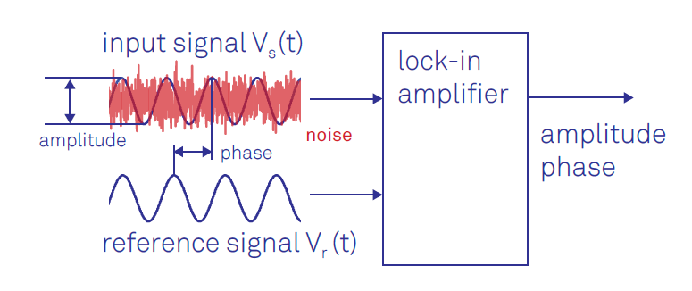
Q: What is the key input-output attribute of the LIA?
A: A lock-in amplifier provides a “DC” (a more accurate term would be “baseband”) output proportional to the slowly or fast-changing signal under investigation. It does this by implementing synchronous demodulation of the desired signal, using the chopper or other modulating signal source as its reference.
Q: What is the key part f the LIA?
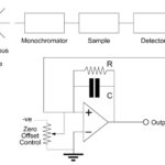
A: The key of the LIA is the phase-sensitive detector (also called a mixer) which functions as a demodulator (Figure 1).
The detector multiplies two signals together – here, a reference signal and the signal under evaluation. This mixed output is a low-pass signal which can be more-easily filtered to yield the required DC output (Figure 2) shows the LIA arrangement when used for the photodetector output-sensing experiment.
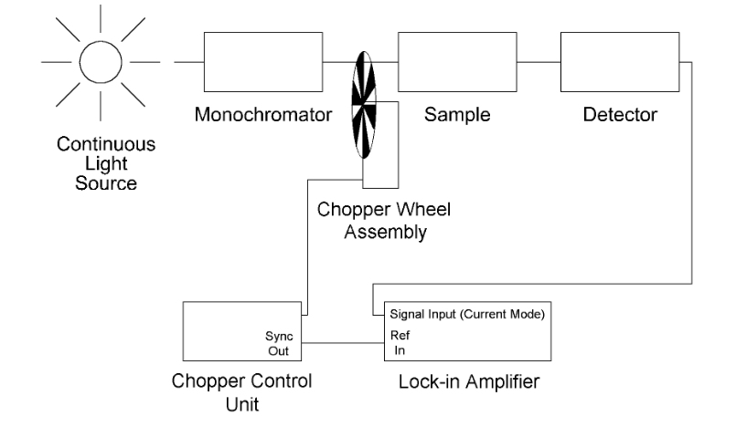
A: It can come from a local signal source in the LIA, or it can be the same signal driving the chopper wheel (in this example). In fact, the LIA can be used to generate that chopper-driving signal if appropriate.
Q: What advantages does using the LIA as a signal source offer?
A: First, the demodulation is “perfectly” synchronized to modulation of the signal of interest (of course, nothing is ever perfect, but it can be very close), thus yielding high-quality demodulation. Second, if the chopping or other modulating reference has errors or drifts, as they all do, the demodulation will still be synchronized since the reference signal, and the signal of interest are both using the same reference.
Q: This looks similar to some of the demodulation schemes used in some communication systems, but is it?
A: There are many similarities between the LIA and the phase lock loop (PLL), a widely used demodulation architecture for analog and digital communication channels. The difference in the details, but the principle of synchronization of the demodulation process to the input-signal carrier is the same. The LIA is also referred to as having a homodyne architecture, especially by those with a communications receiver background due to the many similarities between the LIA and the synchronous demodulation of communications systems. A homodyne design uses only one frequency to up- or down-convert the signal, in contrast to the heterodyne approach, which uses an intermediate frequency.
Q: What is the major difference?
A: In the LIA used for experiments, the test arrangement almost always has direct access to the driving reference signal (carrier), and therefore, that signal is known. Thus, any changes in that signal will automatically sync with the signal to be demodulated at the mixer. In contrast, in communication links, the PLL in the receiver does not have access to the originating carrier itself and must first extract (recover) it – which the PLL does – and then use it for demodulation.
This recovery is never perfect and adds uncertainty (noise) to the demodulation process, thus reducing the signal-to-noise ratio (SNR) and increasing bit error rate (BER). For this reason, the LIA has a much easier challenge than the communications-link PLL scenario. This difference is yet another manifestation of classic “signal theory”: the more you know about a signal with increased certainty (in this case, the carrier frequency and phase), the better the system can do at demodulating the unknown signal from that carrier.
Q: Is there another benefit to the LIA architecture?
A: Yes, since the reference signal is known, the LIA can function effectively over a very wide dynamic range of signal amplitudes. LIAs which can function over as many as seven orders of magnitude are common.
Q: What are the frequencies of operation for LIAs? What are some figures of merit?
A: LIAs are available for processing using signals into the tens of megahertz (MHz), and some go up to several hundred megahertz. Of course, many real-world applications, especially biological and mechanical ones in contrast to optical ones, are in the much-lower range of tens of kilohertz. Among the key parameters which characterize LIA performance are drift, phase noise, and dynamic reserve (similar to dynamic range).
Q: What else can an LIA do?
A: It can be used for other precision measurements. For example, adjusting the phase of the reference signal going to the phase detector/demodulator can provide accurate phase-shift measurements on the sensor input signal. Further, by adjusting some of the operating parameters of the LIA, such as those of low-pass filter which follows the phase detector, the LIA can also be used as a noise-measuring unit, a vector voltmeter, and even a spectrum analyzer.
Q: What are some of the key shifts in LIA design in the last decades?
A: Again, the situation is analogous to advances in PLLs. There are several notable advances over earlier all-analog implementations for LIAs, which are most often “benchtop” instruments. First, the user interface is digital with push-button control of settings, digital readouts, and USB and Ethernet connectivity. Some LIAs can provide two reference outputs simultaneously, which allows setting up ratiometric arrangements so that errors can self-cancel. (The ratiometric scheme is a well-known measurement approach in which signal ratios are used rather than absolute values, thus self-canceling many drift and related errors; it is the basis for the venerable Wheatstone bridge, for example.)
Second, the phase detector at the core has transitioned from an all-analog circuit to a largely digital one, just as with PLLs. While the front-end amplifier for the sensed signal is still analog, as it must be due to the physics reality, that signal is digitized immediately after the amplifier and then goes to an all-digital phase detector. At the same time, the reference signal which the LIA generates is also created digitally, with full control over all its settings and parameters. These higher-end LIAs also embedded digital signal processing (DSP) algorithms and techniques to enhance their performance and useful analysis features.
LIAs with analog phase detectors are still used as they offer the lowest noise for the signal-processing core. These “analog” systems are hybrids and still have overall digital control of parameters and a digital user interface.
Q: What does a sophisticated, commercially available LIA look like, and cost?
A: LIAs are offered by many higher-end lab-instrumentation companies, such as Stanford Research Systems (SRS), Zurich Instruments, and AMETEK Scientific Instruments (Perkin Elmer formerly owned their product line), with prices beginning at around $2000.
A representative mid-range LIA is the SRS SR830 Lock-In Amplifier, an LIA with an analog phase detector (~$5000) and full digital supervisory control and readouts (Figure 3).
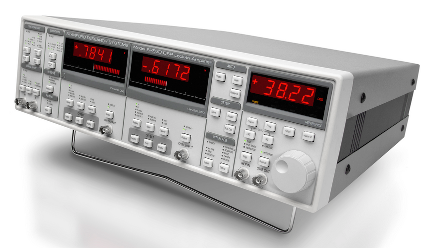
It can measure AC signals as small as 2 nanovolts in the presence of much larger noise levels. The SR830 uses very clean sine-wave multipliers, which are inherently free of unwanted harmonics, which would degrade performance for highest-precision applications. It provides a lock-in reference frequency of 1 mHz (yes – millihertz) to 102.4 kHz (other SRS units go to tens of MHz and even up to 200 MHz).
The unit has just 6 nV/√Hz of input noise along with 100 MΩ input impedance. The input can be configured as a voltage input or as a current input with 106 V/A gain. It features over 100 dB of dynamic reserve, 5 ppm/°C stability, 0.01-degree phase resolution, and filter time constants from 10 µsec to 3 ksec to allow users to trade-off maximum noise reduction versus faster response.
Although this has been a qualitative, non-equation-based discussion of the LIA, the LIA shares another attribute with its close cousin, the PLL: both have been analyzed in great detail using quantitative techniques to provide detailed insight into their performance, capabilities, and impact of inevitable imperfections and noise. Some of the references cited below provide these perspectives and analyses, as well.
Related EE World articles
- Multi-device synchronization for lock-in amplifiers and arbitrary wave generators
- Lock-in amps get AM/FM modulation option
- FAQ: What is Phase Locked Loop (PLL)?
References
- Ametek Technical Note TN100, “What is a Lock-in Amplifier?”
- Perkin Elmer (now Ametek) Technical Note TN102, “The Analog Lock-in Amplifier”
- Perkin Elmer (now Ametek) Application Note AN 1003, “Low Level Optical Detection using Lock-in Amplifier Techniques”
- Zurich Instruments, “Principles of lock-in detection” (includes video tutorial)
- Zurich Instruments, “Principles of lock-in detection and the state of the art”
- Stanford Research Systems, Application Note 3, “About Lock-In Amplifiers”
- Lehigh University, “Lock-in Amplifier and Applications”
- All About Circuits, “Basic Fundamentals of Lock-In Amplifiers”
- SPIE, “Applications of Lock-in Amplifiers in Optics”
- Journal of Chemical Education, “Low-Cost, High-Performance Lock-in Amplifier for Pedagogical and Practical Applications”
- Science Direct, “Application of Lock-In Amplifier on Gear Diagnosis”
- American Journal of Physics, “A basic lock-in amplifier experiment for the undergraduate laboratory”
- University of Tennessee, “A Lock-In Amplifier for Fluorescent Light Detection”