Stepper motors can be configured for unipolar or bipolar drive; each approach has different performance attributes and tradeoffs.
The previous part of this article presented the basics of different coil windings and connections for unipolar and bipolar stepper-motor configurations. As in most engineering situations, the next questions are: what is the impact of these differences? What does each approach offer concerning benefits and drawbacks?
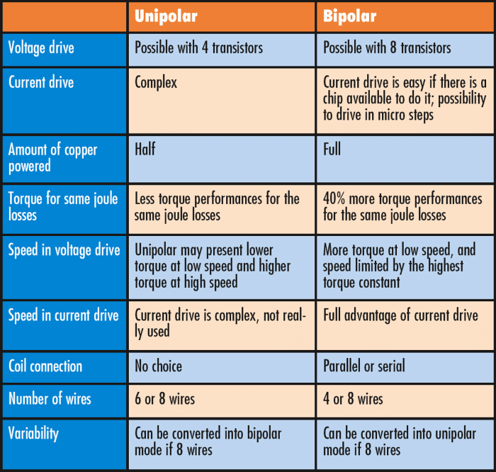
With unipolar control, only half of the phase is powered at a time, so the current only uses half of the total copper-winding volume, while bipolar drives use all the copper per phase. This has implications for cost and weight versus performance, with speed and torque performance usually the key parameter of interest.
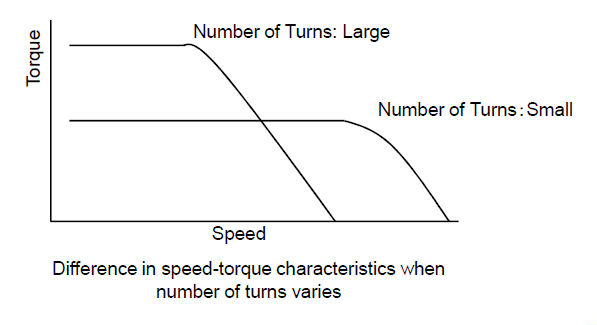
Torque is proportional to the product of the driving current, and the number of winding turns on the coil. Torque is higher with a higher number of turns but “levels out” at high speed, limiting the maximum speed at which stepper motor can run effectively and provide needed torque. The reason is that the coil self-inductance limits the rate at which the drive current to the motor can change, which limits torque at higher speeds. On the other hand, the self-inductance is less with fewer turns, so the torque is less at lower speeds but is maintained at higher speeds (Figure 1).
Note that toque also has an inverse proportional relationship with respect to speed and inductance:
Torque α Motor Supply Voltage/(Motor Speed × √Motor Inductance).
From a modeling perspective, voltage-related analysis can be difficult to resolve since motor coils are current-driven magnetic devices; when driven by a voltage source, the relationship between applied drive voltage and resultant coil current is nonlinear and complicated to model.
Due to their more effective use of the coil winding, bipolar motors generally have more torque and are more efficient than unipolar motors. In contrast, unipolar motors use only half of each winding coil at a given time, resulting in lower torque and efficiency.
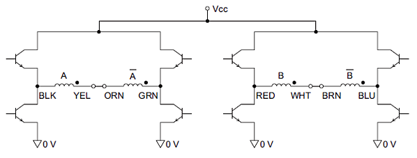
Even bipolar motors offer a choice in configuration with tradeoffs, as their coils can be connected “bipolar-series” or “bipolar-parallel.” Bipolar-series uses the full coil winding, so the motor can deliver more torque than unipolar (Figure 2). Consequently, however, the coil’s inductance also increases by four, so the torque – which is largely limited by the inductance – drops off and does so quickly at higher speeds.
An alternative is the bipolar-parallel wiring approach, which uses the full coil but increases the torque by about 40 percent compared to unipolar arrangement (Figure 3). The paralleled coils offer lower inductance so that the torque can be maintained at higher speeds. [Think back to circuit basics: inductor values combine like resistance values. When inductors are connected in series, the total inductance is the sum of the individual inductances; when inductors are connected in parallel, the total inductance is less than any individual inductor’s inductance.]
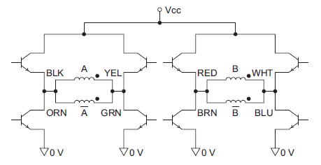
However, there is no “free lunch” when getting this additional torque as the suppled current must also increase by about 40 percent. This affects sizing and thermal aspects of the motor-drive components. In many designs, the low inductance, high current and torque, and low voltage of bipolar-parallel make it a good combination for the best overall torque performance.
The table (Figure 4) summarizes the major attributes of basic unipolar and bipolar approaches.
It may seem sensible for vendors to simply offer just one type of motor with all the possible coil ends “exposed” and available so users can configure the stepper-motor coils to whichever arrangement is needed, thus simplifying the bill of material and inventory. This would be somewhat analogous to the field programmable gate array (FPGA).
After all, a six-wire motor can be wired in unipolar or bipolar-series and an eight-wire motor can be wired in unipolar, bipolar-series, or bipolar-parallel. This is sometimes done, and vendors usually offer a configuration chart showing which wire leads need to be connected to other leads to create the various configurations.
There’s much more to motors in general, of course, and stepper motors in particular. Most vendors of these motors offer board product lines and so can be objective about getting a suitable fit rather than “forcing” a solution. Since they know that many designers are not experts in motor-parameter tradeoffs, they offer useful application notes on stepper-motor basics, sizing, selection, thermal considerations, optimization, and other topics; much of this material is vendor-independent and applies motors from any supplier. They also have application engineers who are specialists in both the qualitative realities of motor selection and use as well as the quantitative specifications.
The final part of the article will look at some ICs available for control of stepper motors.
Related EE World content
- Overcoming stepper motor design challenges in 3D printers
- Stepper motor driver IC simplifies low cost, power efficient designs with noiseless operation
- Basics of AC, DC, and EC electric motors (Part 2) — EC and stepper
- Thermal printers, Part 4: Components and circuitry
- Basics of motion-control profiles, Part 3: Implementations
- Basics of motion-control profiles, Part 2: Ramp profiles
- Basics of motion-control profiles, Part 1: Context
- Motor fundamentals and DC motors
- Basics of AC, DC, and EC electric motors, Part 1— AC and DC
External References
- Portescap (via Tech Briefs), “Bipolar and Unipolar Drives for Stepper Motors: A Comparison“
- Tech Explorations, “The difference between unipolar and bipolar stepper motors“
- Oriental Motor, “Wiring Basics: Unipolar vs Bipolar“
- Oriental Motor, “Unipolar/Bipolar Connections for 2-Phase Stepper Motors“
- Oyostepper, “Some differences between bipolar and unipolar stepper motor“
- Electrical4U, “Bipolar Stepper Motors: What is it?“
- Texas Instruments, “Drive unipolar stepper motors as bipolar stepper motors with a simple wiring reconfiguration“
- Texas Instruments, “Stepper Motor 1: Basics”
- Texas Instruments, “DRV8847 data sheet“
- Performance Motion Devices, “Magellan MC58113 Series Motion Control ICs“
- Performance Motion Devices, “Magellan Motion Control IC: MC58113 Electrical Specifications“