by Craig Lombard, Electrical Engineering Manager, CET Technology
The intent of this write-up is to provide engineers with an understanding of how a few of their most useful equations are derived. Most engineers are familiar with Faraday’s Law of Induction and from this law some of their most important and well-used equations are created. The equations derived in this write-up are of particular use to transformer and inductor design engineers.
We can use Faraday’s law of induction to find the voltage transformer equation, the current inductor equation and the well-known formula that relates voltage and current for an inductor.
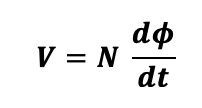
Faraday’s law of induction (ignoring the negative sign):
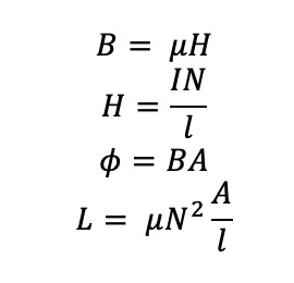
First, let’s get the relation between voltage, current and inductance…..
 What this equation tells us is that the voltage leads the current in an inductor ideally by 90 degrees. Let’s say the current is described by a sine wave with no phase offset, the derivative of which is a cosine wave. At time t=0, the current would be zero while the voltage would be at its MAX value. This is shown graphically below.

Here’s what relations were used to get that above equation.
This equation is well known and well used in electrical engineering, although many EE’s may not know where it comes from.
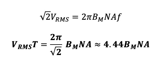
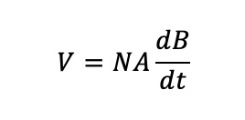
Now let’s get the transformer voltage equation, also well-known and used by transformer engineers.
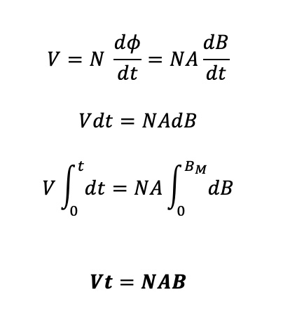
Where B is the core flux density reached in time period t.
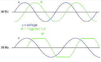
This equation tells us that for some applied volt-sec’s, the product of the turns, flux density and core area must be at least the size of the applied volt-sec’s or your flux density will attempt to be larger and the core may saturate. Let’s say you design for some voltage at 60Hz, what happens when someone uses 50Hz instead? The applied volt-sec’s are increased and so the core flux also tries to increase. As you can see below the core flux tries to be greater at 50Hz than at 60Hz but in fact the core is saturating as it cannot hold any more flux.
It is always best to try and set the product of turns, core area and flux density larger than the applied volt-sec’s to ensure the core will not saturate. In other words…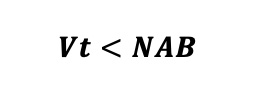 Now if a sinusoid is applied to the transformer primary, we can go back one step and solve the equation a bit differently……let’s use this below….and since our applied voltage is sinusoidal then the flux in the core must also be sinusoidal. This means we can write B just as you see below this voltage equation….and the applied input voltage, V, as just below this:
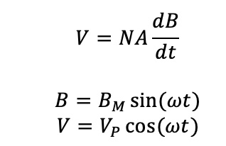 So…
So…
 Just to make something clear, I defined the flux density as a sin and the voltage as a cos because the flux density is a direct cause of the current flow. Current increases and so does flux, in step and in phase. While the voltage that causes that current is applied to the transformer primary, which is an inductor, and all electrical engineers know that current and voltage are 90 degrees out of phase in a perfect inductor so this was not simply mathematically convenient, it was in fact quite necessary.
Now, most times we are told the primary voltage value in terms of its RMS value, not its peak value (Vp), so let’s put that in above and complete our derivation.
 This is good for sinusoids, now let’s do it again for an applied square wave.
 Now for an applied square wave, the voltage is constant until it changes polarity, so if the voltage is constant then the flux density must be triangular because the derivative of B must be a “step” or constant value……since the triangle wave slope can be written as a linear change in rise over run, we will do that now….furthermore since B is triangular it is changing from some positive MAX to some negative MAX every half period when the voltage changes state from positive to negative….let’s call this peak value it reaches Bm and so the change is in two of these in half a period.
 And this is good for square waves applied to the transformer primary.
 This is all good and helpful for transformers….know your MAX applied volt-sec’s to ensure the core stays at some MAX flux density and hence does not saturate but what about inductors?
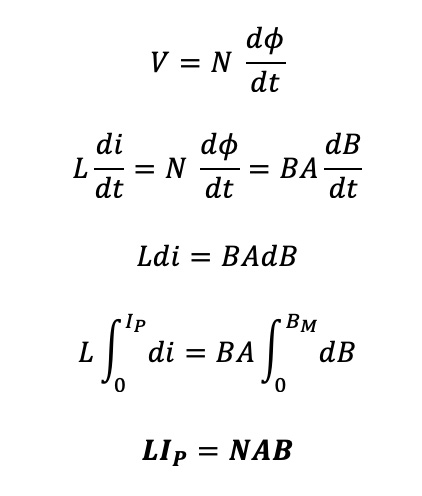
Often we are told an inductance that is desired at some current flowing through it, so let’s get a formula that is helpful for inductors as well.

I used the equation first derived relating inductance and current to voltage and substituted that into Faraday’s law of induction. All of these derived equations are used frequently by transformer engineers and are quite useful. They are all derived from Faraday’s law of induction — a very useful law itself.