A 680 pf capacitor is used to make a low-pass filter, removing high-frequency harmonics in order to transform a square wave into a crude sine wave.
Hi and welcome to our 64th Test and Measurement video. Today we’ll look at an easy and very inexpensive way in this Tektronix MDO 3000 Series oscilloscope to convert a square wave to a sine wave, the understanding being that the sine wave is far from the product of the sine function that we see in the output of a rotary generator or a quartz-regulated frequency synthesizer.
Fourier Transform folks understand that any finite non-sinusoidal waveform resolves into the sum of a finite number of sine waves. As a matter of fact, if we look at the frequency spectrum of a square wave in an FFT mode oscilloscope display, as opposed to that of a sine wave, there is a large number of harmonics, diminishing in amplitude as the frequency increases with respect to the fundamental, until eventually they are lost below the noise floor of the instrument. Presumably they go a long way even if not infinitely.
This in mind, it would seem probable that a sine wave could be isolated by passing the square wave signal through a low-pass filter, eliminating the higher frequency harmonics. A simple, not to say primitive low-pass filter can be constructed by shunting a capacitor across the signal.
It is a little bit difficult to do this using the unbroken BNC connection. You could obtain a BNC socket with wire pigtails or alligator clips. This is called a breakout cable. Tektronix told me that the AFG on the MDO can source only a small amount of current, so there should be no risk in connecting it to a small load. The output can be modeled on a 50-ohm series resistor, so it is safe to drive anything from an open to a short.
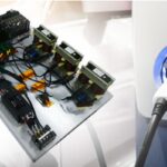
An alternative that has no apparent downside other than that frequency and other parameters cannot be changed is to connect the oscilloscope to a square wave output from a demo board. A Tektronix TPP 1000 10:1 probe is thus acquiring a square wave and applying it to the Channel One analog input port, and the signal is displayed. On a trial and error basis, various capacitors are shunted across the demo board square wave output. A capacitance that is too low has no visible effect on the signal, while a capacitance that is too high converts it to a noisy DC. If the exact value is not available, two or more capacitors can be placed in parallel, in which case the capacitance values are additive.
For this particular signal and considering the impedance of the oscilloscope at the probe tip, 680 pF shunted from probe tip to ground was found to make a crude sine wave. It won’t run a 100 hp induction motor, but it does demonstrate the way in which a capacitor in shunt configuration can suppress high-frequency harmonics to reveal a sinusoidal fundamental.
Thanks for watching. New videos are added periodically, so check back frequently.
The post VIDEO: Converting Square Wave to Sine Wave appeared first on Test & Measurement Tips.