In a simpler time there wasn’t a great need for electronic simulation because equipment composed of discrete components could easily be bread boarded and powered up to try out ideas. This approach is now unfeasible thanks to billion-component ICs, multi-gigahertz bandwidth requirements, parasitic impedances, and electromagnetic interference issues.
Rather than manually building and testing multiple versions of each project prior to a prototype, the method of choice is to perform an electronic simulation. Fortunately, enabling software with abundant supporting documentation is available online. The best perspective on all of this is historical, beginning with the innovative application known as SPICE, for Simulation Program with Integrated Circuit Emphasis.
SPICE is a highly successful open-source analog electronic circuit simulator that predicts circuit behavior, where non-linear dc, non-linear transit, and linear ac signals are involved. Circuit components include resistors, capacitors and inductors. Voltage and current sources may be dependent or independent. Transmission lines (lossy and lossless), switches and uniform distributed RC lines are included as well as semiconductors such as diodes, bipolar junction transistors, junction FETs and MOSFETs. Built-in models for semiconductor devices let users plug-in parameter values and obtain immediate readouts.
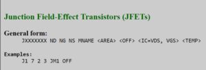
Here’s how you’d specify a specific JFET in a SPICE model. ND, NG, and NS are the drain, gate, and source nodes, respectively. MNAME is the model name, AREA is the area factor, and OFF indicates an (optional) initial condition on the device for dc analysis. There’s also an (optional) initial condition specification, using IC=VDS, VGS is intended for use when a transient analysis is desired starting from other than the quiescent operating point. The (optional) TEMP value is the temperature at which this device is to operate.
SPICE originated at UC Berkeley’s Electrical Engineering and Computer Science campus. The current version is SPICE3, which differs from earlier efforts in that it recognizes MOSFET technology. From the start, SPICE has been open source, meaning the code is freely available. As a consequence, many variations have been created with different user interfaces and add-ons. Some of them are free and others must be purchased. Limited trial and student editions are available for download on the Internet, and documentation is abundant.
Input data and command lines for SPICE are typed on a computer keyboard and saved as a text file. Subsequently, the contents of the file are processed by one of the available SPICE applications. SPICE source files, known as “netlists,” must be compiled according to certain conventions. If there is an error in syntax, the program may yield false results or fail to work at all.
The SPICE output is also plain-text, consisting of an ASCII text file, so it can be viewed on any computer. The finished product can now be saved in a word processing program and edited for readability.
The types of analysis performed by SPICE divide into seven basic categories. The most fundamental of these, consisting of a preliminary look at the circuit under investigation, is the dc analysis. All of the virtual inductors in the circuit are shorted and the capacitors are opened, so functionally they do not exist. The dc analysis then takes place, ascertaining the initial state of the circuit to provide perspective for the subsequent ac analysis.
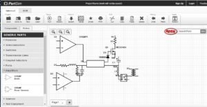
It’s possible to find a lot of free SPICE-type simulators online. This one is called PartSim and lets users develop a parts list from components stocked by the electronics distributor Digi-Key.
Information that may be obtained at this juncture includes the dc small-signal ratio of output to input. Input and output resistance, with reactance eliminated from the equation, is also present. DC transfer curves are generated as the user steps an independent voltage or current source over a desired range so that the dc output variables are displayed and may be recorded.
SPICE next performs the ac small-signal analysis. For this operation, inductors and capacitors previously disabled by opening or shorting are restored. AC outputs are computed as a function of frequency. With the dc analysis completed, the user specifies a range of frequencies which are applied at the input(s). Generally, the output is expressed as voltage gain, transimpedance, or other transfer function. If there is only a single ac input, it may be set to unity with the phase at zero. That way the output variables are equal to the transfer function of the output variable compared to the input.
SPICE also performs a transient analysis. This means time enters the mix. The user specifies the time interval. The dc analysis automatically establishes the initial conditions. Non-time-dependent sources such as power supplies are fixed at their dc level. The user specifies the transient time interval by means of the .TRAN control line.
Pole-zero analysis is time consuming and does not always work, but for what it is worth there is substantial information to be gained. SPICE computes the poles and/or zeros in the small-signal ac transfer domain. It begins by determining the dc operating point and from there ascertains the linearized small-signal models for non-linear devices that are in the circuit under investigation. This enables the user to discover the poles and zeros of the transfer function.
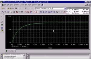
SPICE programs can be set up to generate scope-like displays of circuit behavior. An example is the Probe feature in a program called PSpice. The PROBE statement included in the PSPICE Netlist generates a file, PROBE.DAT, for viewing the analysis on the computer monitor. If the PROBE program is executed, an output can be obtained as shown here. The PROBE statement is included in the netlist so PSPICE will generate the file PROBE.DAT for viewing the ac analysis as a function of frequency on a computer monitor.
Transfer functions fall into two categories: the ratio of output voltage to input voltage and the ratio of output voltage to input current. From these transfer functions the poles and zeros of input and output impedance and voltage gain can be discovered. Input and output ports are now specified as node pairs.
Aside from transmission lines, pole-zero works with familiar devices: resistors, capacitors, inductors, linear-controlled sources, independent sources, BJTs, MOSFETs, JFETs and diodes.
The SPICE function known as small-signal distortion analysis is necessary because of the non-linear nature of many circuit and device configurations. To analyze the situation, SPICE quantifies harmonics and intermodulation signal components at the output.
Sensitivity analysis is calculated by looking at operating point and small-signal output with respect to circuit variables, notably model parameters. Each parameter of each device is perturbed individually.
SPICE performs the all-important function of noise analysis by calculating the amount of noise contributed by each device within the circuit. It also quantifies the amount of noise present at the input. This analysis takes place for all frequencies within a specified range.
SPICE integrates all these noise values to arrive at a Gaussian display that will ascertain whether the amount of noise is acceptable or conversely if the product design will require revision – all this before any prototype is built.
SPICE extends the types of analysis described above by hypothesizing a range of temperatures. The initial operating temperature, comprised of ambient and device-generated thermal energy, is assumed to be 27°C. However, this temperature may be changed by the user by means of the TNOM parameter on the .OPTION control line. A number of device-specific formulae provide temperature coefficients and curves that are applicable in specific instances.
Because SPICE is open source, there are many available variations with special interfaces. Consequently, a single set of instructions for deploying SPICE in the classroom or laboratory is not a realistic expectation. However, here are some general observations:
To initiate a SPICE analysis, the user describes the circuit that is to be simulated by constructing a set of element lines. They define the model parameters and the run controls. The input file has a first line, which is the title, and the last line must be .END. The order of the intermediate lines is not fixed, as long as all elements are defined.
Circuit elements are specified as element lines. Each element line is composed of the element name, connected circuit nodes and the element’s electrical parameters. The first letter of the element name stands for the element type. R, for example, denotes resistor. The element name can contain additional characters.
In each line, there may be multiple fields, which are separated by one or more blanks or some specific characters. To continue a line, enter + in column one of the following line. SPICE resumes reading at the field that follows.
SPICE recognizes command lines that can be deployed by the user to view results of the electronic simulation, and when this is done, the purpose of the program has been fulfilled.
The post When waveform read-outs come from a SPICE simulator appeared first on Test & Measurement Tips.

