• Skip to primary navigation
  • Skip to main content
  • Skip to primary sidebar
  • Skip to footer

Electrical Engineering News and Products

Electronics Engineering Resources, Articles, Forums, Tear Down Videos and Technical Electronics How-To's

  • Products / Components
    • Analog ICs
    • Battery Power
    • Connectors
    • Microcontrollers
    • Power Electronics
    • Sensors
    • Test and Measurement
    • Wire / Cable
  • Applications
    • 5G
    • Automotive/Transportation
    • EV Engineering
    • Industrial
    • IoT
    • Medical
    • Telecommunications
    • Wearables
    • Wireless
  • Learn
    • eBooks / Handbooks
    • EE Training Days
    • Tutorials
    • Learning Center
    • Tech Toolboxes
    • Webinars & Digital Events
  • Resources
    • White Papers
    • Educational Assets
    • Design Guide Library
    • Digital Issues
    • Engineering Diversity & Inclusion
    • LEAP Awards
    • Podcasts
    • DesignFast
  • Videos
    • EE Videos and Interviews
    • Teardown Videos
  • EE Forums
    • EDABoard.com
    • Electro-Tech-Online.com
  • Bill’s Blogs
  • Advertise
  • Subscribe

What are common ways to protect a sensor from harmful exposure?

May 31, 2017 By Randy Frank Leave a Comment

For a sensor, the amount of harmful exposure it receives from the environment and harmful constituents in the measuring process depends on what is being sensed and the environment itself. Different packaging is required to cope with and survive the specific situation. Two major considerations for protection are at the sensing element/transducer level or at the sensing module level.

Today, microelectromechanical systems (MEMS) technology provides many different types of sensing/transducer elements. MEMS sensors are based on integrated circuit/semiconductor processing. The differences in MEMS sensor packaging depends on sensors that are isolated from the environment and those that must specifically interact and come in contact with the measurand.

At the silicon level for MEMS devices, packaging approaches/technologies included over molded, exposed die surface and cavity designs. Packaging materials are commonly plastic for high-volume applications and for more demanding applications, metal can and ceramic materials are used.

In a factory environment, a sealed sensor package with minimum exposure to harsh chemicals, such as a sensor mounted on a printed circuit board inside a module designed for the environment, may strictly rely on a high-volume plastic package.

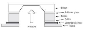
In contrast, a sensor that must contact a media such as water has different design considerations. For example, when a pressure sensors must interface to substances beyond dry air, one common recommendation is measuring the pressure from the back side. The top side of the pressure sensor die has the sensing elements and potentially other circuitry that cannot survive exposure to water. As shown in the figure, the sensor can survive in the application as long as the media providing the backside pressure does not have a detrimental impact to the silicon, plastic and other materials in the sensing element stack.

Materials impacted by applying back-side pressure. Source: Understanding Smart Sensors, 3rd Edition.


One of the common solutions for isolating the top surface of a pressure sensor is a protective coating such as parylene that is applied by a vapor deposition polymerization process. The parylene allows pressure to be transmitted to the top side of pressure sensor.

At the module or end-packaging level, epoxy encapsulation and O-rings for sealing are among the packaging techniques used to provide increased protection to a sensor.

To address the harshest applications where an IP69K rating is required, the materials get rather specific. The packaging housing is frequently a hermetically-sealed stainless steel such as 316, or an FDA-grade with a molded connector to attach to an external cordset/cable.

Polybutylene terephthalate (PBT) thermoplastic housing or cast aluminum housing can also be found as packaging materials for IP69K rated sensors.

These are just a few of the examples of matching the sensor’s packaging capabilities to its application requirements. In many cases, a sensor supplier may have extensive knowledge of its sensors’ capabilities to survive specific applications.

You Might Also Like

Filed Under: MEMS & Sensors, Sensors

Reader Interactions

Leave a Reply Cancel reply

You must be logged in to post a comment.

This site uses Akismet to reduce spam. Learn how your comment data is processed.

Primary Sidebar

EE Engineering Training Days

engineering

Featured Contributions

Integrating MEMS technology into next-gen vehicle safety features

Five challenges for developing next-generation ADAS and autonomous vehicles

Robust design for Variable Frequency Drives and starters

Meeting demand for hidden wearables via Schottky rectifiers

GaN reliability milestones break through the silicon ceiling

More Featured Contributions

EE Tech Toolbox

“ee
Tech Toolbox: 5G Technology
This Tech Toolbox covers the basics of 5G technology plus a story about how engineers designed and built a prototype DSL router mostly from old cellphone parts. Download this first 5G/wired/wireless communications Tech Toolbox to learn more!

EE Learning Center

EE Learning Center
“ee
EXPAND YOUR KNOWLEDGE AND STAY CONNECTED
Get the latest info on technologies, tools and strategies for EE professionals.
“bills
contribute

R&D World Podcasts

R&D 100 Episode 10
See More >

Sponsored Content

Designing for Serviceability: The Role of Interconnects in HVAC Maintenance

From Control Boards to Comfort: How Signal Integrity Drives HVAC Innovation

Built to Withstand: Sealing and Thermal Protection in HVAC Sub-Systems

Revolutionizing Manufacturing with Smart Factories

Smarter HVAC Starts at the Sub-System Level

Empowering aerospace E/E design and innovation through Siemens Xcelerator and Capital in the Cloud

More Sponsored Content >>

RSS Current EDABoard.com discussions

  • The Analog Gods Hate Me
  • Apc 650 upa
  • CST Studio RAM error
  • MCP23017 what is the typical output voltage at logic Hi?
  • Battery Deep Discharge – IC Workarounds?

RSS Current Electro-Tech-Online.com Discussions

  • Simple LED Analog Clock Idea
  • The Analog Gods Hate Me
  • Wideband matching an electrically short bowtie antenna; 50 ohm, 434 MHz
  • PIC KIT 3 not able to program dsPIC
  • Parts required for a personal project
Search Millions of Parts from Thousands of Suppliers.

Search Now!
design fast globle

Footer

EE World Online

EE WORLD ONLINE NETWORK

  • 5G Technology World
  • Analog IC Tips
  • Battery Power Tips
  • Connector Tips
  • DesignFast
  • EDABoard Forums
  • Electro-Tech-Online Forums
  • Engineer's Garage
  • EV Engineering
  • Microcontroller Tips
  • Power Electronic Tips
  • Sensor Tips
  • Test and Measurement Tips

EE WORLD ONLINE

  • Subscribe to our newsletter
  • Teardown Videos
  • Advertise with us
  • Contact us
  • About Us

Copyright © 2025 · WTWH Media LLC and its licensors. All rights reserved.
The material on this site may not be reproduced, distributed, transmitted, cached or otherwise used, except with the prior written permission of WTWH Media.

Privacy Policy