Non-contact sensing of a nearby object’s linear or rotary position in an electrically and mechanically harsh environment is a common system requirement. There are several ways to meet this objective, including sensors based on the Hall effect, the magnetorestrictive effect, and magnetic coupling.
One widely used approach is inductive proximity sensing, which is effective, accurate, and rugged. Modern electronics greatly simplifies its implementation and makes it even more attractive in terms of performance, practicality, and cost. This FAQ will look at the inductive position sensor and circuitry which can provide this capability.
Q: What is inductive sensing?
A: There are actually three types of such sensing: the high-frequency oscillation type, which indirectly uses electromagnetic induction, the magnetic type using a magnet, and the capacitance type using the change in capacitance. We will focus here only on the first one.
Q: Why do you say “indirectly”?
A: Inductive sensors do not measure inductance itself; saying they do is a slight misconception of a misnomer. Instead, they use the electromagnetic induction of a magnetic field in a metal target along with the well-known properties of an air-core transformer (Faraday’s law). This allows the sensor to locate the disturbance of this magnetic field by the electrically conductive target. Note that the metal target does not have to be magnetic (ferrous); non-ferrous metals such as aluminum will also work.
Q: Where at these sensors used?
A: They are used in many industrial and other challenging environments. One of the most common applications is measuring the position and rotation of a motor’s shaft (rotor) by sensing the gear teeth present. These sensors are widely used in automotive applications, especially the hood or near the engine, for example.
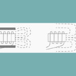
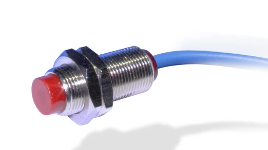
Q: What does this sensor look like?
A: It looks like a standard bolt, and they are available in variable diameters which different ranges and sensitivities (Figure 1). One of the practical advantages of this sensor is its ease of installation, as it screws into a standard threaded hole and then can be firmly attached to a bracket or enclosure with a matching nut or nuts.
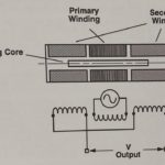
Q: How does this transducer function?
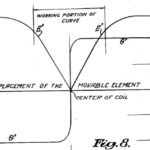
A: There is a primary coil which is excited by a frequency (typically between 1 and 5 MHz) to create a magnetic field, and two secondary coils are used to detect this magnetic field (Figure 2). In turn, these coils transform the magnetic field into a voltage – think Faraday’s law and transformer. (Note the similarities between the inductive position sensor and the LVDT (see Related EE World Content at the end). A metal target placed in this magnetic field will have eddy currents induced in it that oppose the magnetic field, increase the inductor current flow, and change the induction relationship.
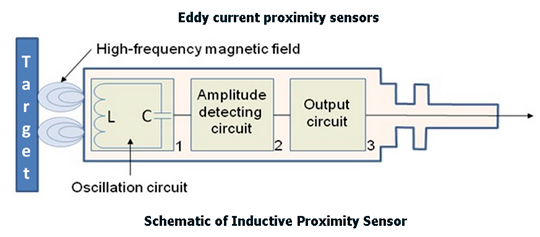
This change has the effect of attenuating oscillation. The sensor detects this change and damping of the oscillation status via the amplitude detecting circuit. The two receiving coils detect different voltages, and the target’s position can be determined by the ratio of these two receive-coil voltages. A threshold circuit then generates an output signal when this ratio exceeds some preset limit.
Q: What are some of the other attributes of this sensor?
A: These are among the most important ones:
- Rugged and reliable: it is entirely enclosed with no exposed elements. Also, similar to the LVDT, the sensor itself (excluding the electronics) is an array of wire loops or coils, meaning wide operating-temperature range, shock resistance, and related tolerance for ambient stresses.
- Consistent and repeatable performance: the basic design is rugged, and with proper circuity, the acquired signals will also be consistent in signal strength and thresholds.
- Compact size and ease of installation: the sensing head can be packaged in larger “bolts” and even small screws, which eases placement. The sensing head is at one end, and the wires are at the other, which is a benefit in placement and routing, and this sensor length can range from 5 mm to 600 mm.
- Sensitivity: depending on design specifics, the sensor can easily sense targets as close as a millimeter or less or out to several centimeters. Consistency of resolution is also quite high and be down in the sub-mm and even micrometer range.
- Readings unaffected to dirt and debris: again, the simple mechanical housing keeps things out, while the reading is unaffected by the non-metallic surroundings.
- High resistance to electromagnetic interference: Many of the applications for these sensors involve motors and high currents, such as in HEVs and EVs (with several hundred amps for their traction motors), both of which generate intense stray-magnetic fields. The sensor’s two-coil design means that it senses differentially, and most stray interfering magnetic fields self-cancel at the sensor receiver.
The second part of this article continues the investigation into the inductive proximity sensor.
Related EE World Content
LVDT electronics, Part 1: Excitation and demodulation
LVDT electronics, Part 2: Interface circuitry
Inductance-to-digital converter is presented as industry’s first for position and motion sensing
Battery powered inductive proximity sensor sports 70-ft range
Inductive position sensor targets absolute position apps in industrial motors
Inductive proximity sensors with analog output from Automation Direct
Wireless inductive system 2 for wireless sensor connection
Magnet-free inductive position sensing targets automotive motor commutation
External References
Keyence Corp., “What is an Inductive Proximity Sensor?
Keyence Corp., “Categorization of inductive proximity sensors
Automation.com, “How Inductive Sensors Work”
Fargo Controls, “Operating Principles for Inductive Proximity Sensors
Microchip Technologies, “Robust, Low-Cost and Noise-Immune Motion-Sensing Inductive Sensors
Renesas Electronics Corporation, “IPS2550 Inductive Position Sensor for High-Speed Motor Commutation (Automotive)
Texas Instruments, “LDC1101 1.8-V High-Resolution, High-Speed Inductance-to-Digital Converter”