Accelerometers are deceptively simple-looking devices but are complex electromechanical systems. But there are numerous mechanical, environmental, electronic, and application-related factors to consider when using accelerometers.
This FAQ reviews several of the subtleties that need to be considered when using accelerometers as vibration sensors and closes with a look at the ISO/IEC/IEEE 21451-4:2010 standard for Transducer Electronic Data Sheet (TEDS) formats and how it can be used when deploying accelerometers.
Frequency range and resonance errors
The vibrational energy of accelerometers is often higher in the frequency range between 10 Hz and 1 kHz. There are two primary factors that can limit accelerometer operation at lower frequencies. One can be the low-frequency cut-off of the amplifier, but this is only a problem in extreme circumstances when measuring vibrations well under 1 Hz. The other is the effect of ambient temperature fluctuations which can be especially problematic at low frequencies. Using shear-type accelerometers can minimize the impact of temperature variations at low frequencies.
Some applications can require measurements up to 10 kHz, or higher, and can require special treatment. The upper limit is determined by the resonant frequency of the accelerometer. A general rule is that setting the upper-frequency limit to about one-third of the accelerometer’s resonant frequency will eliminate the concern related to resonance-induced measurement errors. This is less of a concern with small accelerometers that can have resonant frequencies up to 175 kHz.
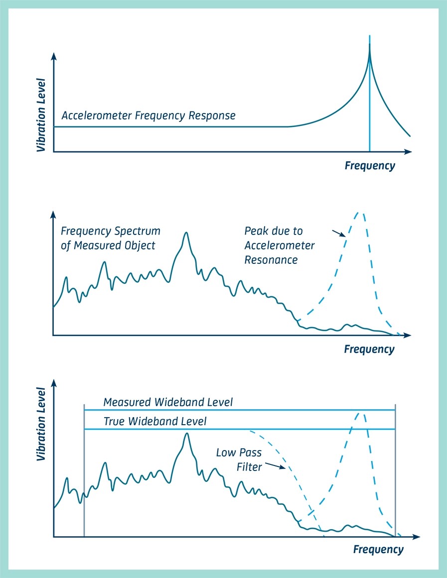
For larger general-purpose accelerometers with higher outputs, resonant frequencies can be as low as 20 kHz. These accelerometers can be subject to resonance errors at high-frequency due to the accelerometer’s inherent resonance. That can result in measurement errors when a wideband reading is made. Choosing a device with a wide frequency range and adding a low-pass filter, often included in vibration sensors and preamplifiers, can reduce the problems caused by accelerometer resonance (Figure 1). Another option, is when measurements are made at low frequencies, high-frequency resonance effects can be mitigated using mechanical filters like a rubber layer placed between the accelerometer and the mounting surface.
Sensitivity
Sensitivity is a key specification for accelerometers. It quantifies the conversion between vibrations and voltage at a reference frequency and is specified in mV/g and is often frequency dependent. For example, if an accelerometer has a sensitivity of 100 mV/g, it produces an output of 1 V when measuring 10 g acceleration. The sensitivity of individual accelerometers is measured during calibration. Since it can be frequency dependent, a full sensitivity calibration can be required across the usable frequency range. Low-sensitivity accelerometers are generally used to measure high-amplitude vibrations and high-sensitivity units are used for low-amplitude applications.
Residual noise
The residual noise level determines the lowest amplitude that a sensor can measure. It’s important to use an accelerometer with an optimal measurement range. Accelerometers with a wider measurement range will also be subject to larger residual noise levels. The internal electronics in Integrated Electronics PiezoElectric (IEPE) accelerometers can provide very high effective dynamic ranges. Charge sensors can offer similar dynamic ranges, but they can be sensitive to noise issues related to cabling and other factors. Capacitive and MEMS accelerometers often have narrower dynamic ranges.
Weight
Accelerometer weight can be a significant consideration due to the mass loading effect. Any mass added to a structure increases the overall mass of the combined structure and changes its dynamic (vibrational) behavior. In general, the weight of the accelerometer should be no more than 10% of the weight of the vibrating element onto which it is mounted.
Mounting
How an accelerometer is mounted can impact its operation, especially its frequency limit. There are many mounting options, four of the most common are:
- Handheld or probe tips
- Magnetic
- Adhesive
- Stud
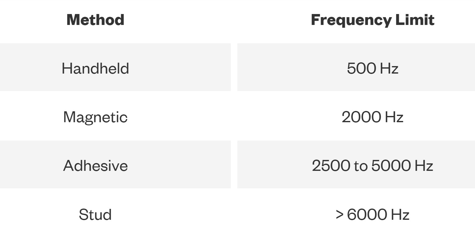
Handheld, magnetic, and adhesive are generally reserved for short-term or spot acceleration measurements. The less secure the attachment, the lower the measurable frequency limit. In addition, adding mass like an adhesive or magnetic mounting base lowers the resonant frequency, limits the usable frequency range, and can reduce the accuracy of an accelerometer. Most accelerometers that are designed for various mounting styles include information in the datasheet on how mounting impacts performance. Stud mounting is the most robust and produces the best overall performance, but requires a hole to be drilled into the mounting surface and is generally used for permanent installations. Examples of the frequency limits for a 100 mV/g accelerometer using different mounting methods are summarized in Table 1.
Environmental constraints
Environmental factors like operating temperature range, humidity, and exposure to chemicals can impact accelerometer performance. In challenging industrial environments, accelerometers packaged in stainless steel are available that can deal with corrosion and chemicals.
The piezoelectric materials used in many accelerometers are temperature dependent and changes in the ambient temperature will cause a change in the sensitivity of the device. The output of piezoelectric accelerometers can vary when they are subjected to temperature fluctuations. These temperature transients can be especially troublesome with low-frequency vibrations or low-level sensor outputs. Shear-type accelerometers where the sensing element is attached between a center post and a seismic mass typically have a lower sensitivity to temperature transients.
Charge mode accelerometers without integrated electronics are best suited for high-temperature operation. Their operating temperature range is only limited by sensing technology and packaging materials. But the lack of integrated electronics means these units can require an external amplifier or charge converter and need low-noise cabling to minimize susceptibility to noise. IEPE accelerometers can eliminate the need for a low-noise cable, but they have lower maximum operating temperatures due to the integrated amplifier.
Thermal management can be important when accelerometers are attached to high-temperature surfaces. For example, a heatsink with thermal grease and a mica washer can be attached between the base and the accelerometer to keep the sensor at about 250 °C, even when the measurement surface is over 350 °C. Forced airflow can provide additional cooling. MEMS and IEPE operating temperatures are limited by the internal electronics, typically from -40 to 125 °C.
Cabling
Cables can be an issue with accelerometers, especially piezoelectric accelerometers with high output impedances. For example, when a coax cable is bent, twisted, or compressed, local chances in capacitance can produce charge transport due to the triboelectric effect. The induced charge transport interferes with measuring low vibrations with charge transducers. Low-noise cables like graphitized accelerometer cables can be used to mitigate this problem. In addition, the cable should be secured with clamps, tape, or glue to reduce the potential for movement.
Strong electromagnetic fields can also result in error signals, especially with charge transducers. The cable should be routed far away from sources of electromagnetic interference such as generators, motors, and switch mode power converters.
IEPE accelerometers don’t generally require special low-noise cables and can be used with standard coax cabling. A third option is to use a proximity probe. In contrast with conventional accelerometers, these probes are non-contact devices. They measure the distance to a target and can be used to monitor vibrations. Proximity probes are often used to measure vibrations in structures like rotating shafts, where it’s not possible to attach a conventional accelerometer.
TEDS compatibility
Smart sensors can employ the technology outlined in ISO/IEC/IEEE 21451-4:2010 “Information technology — Smart transducer interface for sensors and actuators — Part 4: Mixed-mode communication protocols and Transducer Electronic Data Sheet (TEDS) formats.” This standard is based on the IEEE 1451 open standard series for smart sensor communications.
TEDS enables sensors like accelerometers to be used in a plug-and-play manner, eliminating the need for manual setup and installation. A typical TEDS chip is a small EEPROM that includes data like:
- Sensor type
- Serial number
- Model name
- Calibration data
- Manufacturer name
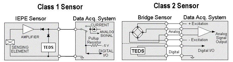
The standard defines two classes of TEDS devices (Figure 2):
Class 1 devices use the same wires for both the analog signals and the TEDS digital communication. When the TEDS data is being read, the sensor output is reversed biased to prevent any interference.
Class 2 devices use separate wires for the analog signal and TEDS digital communication. This is common in retrofit situations when a TEDS chip has been added after the sensor has been produced.
Summary
Using accelerometers as vibration sensors requires careful attention to numerous details related to the environment, the mechanical assembly, cabling, signal conditioning electronics, and other factors to ensure reliable and accurate operation. The incorporation of TEDS technology can speed up the deployment of these sensors.
References
5 rules for installation and mounting of piezoelectric force transducers, HBM
Accelerometer Cabling, Metra Mess- und Frequenztechnik
Accelerometer Signal Cable Basics, The Modal Shop
Differences Between Class 1 and Class 2 TEDS Sensors, NI
Measuring Shock and Vibration with Accelerometer Sensors, DEWEsoft
Measuring Vibration with Accelerometers, NI
Sensors, VibraSens
Piezoelectric Accelerometers, Brüel & Kjær