Pressure sensors today are almost as common as op-amps were in the 1990s. Applications span from consumer smartphones to precision control instrumentation in the world’s most sophisticated process plants. Pressure sensors themselves are not new, but the technology inside and variation of devices are ever expanding. This article helps design engineers get up to speed with the latest in differential pressure (DP) measurement.
A DP sensor is a special type of pressure sensor that measures the change in pressure across two ports on a device. This is different from a static or absolute pressure sensor that would measure pressure using just one port. A barometer or altimeter is the classic example of an absolute pressure sensor, whereas an aircraft airspeed sensor is the classic example of a DP measurement device. DP is also a measure of flow; hence, many applications describe their requirement as a flow measurement.
DP measurement for low-pressure ranges is often used in medical, industrial, and Internet of Things (IoT) applications. DP is measured in units of Pascals (Pa) or inches of water column (inH20)—1.0 Pa = 0.00402 inH20. A high-accuracy DP measurement is one that achieves an accuracy better than 0.1 Pa.
Some typical end applications of flow and DP include:
1. Medical Devices: For example, in-home, small machines known as continuous positive air pressure (CPAP) use flow sensors to help regulate airflow to the user, which helps treat sleep apnea.
2. Residential Metering: Flow sensors are often used for measurement and accounting of natural gas flow into homes and building throughout the world.
3. Appliances: DP can be found in residential, commercial, and industrial gas burners to control gas flow into a burner system. They are also found in HVAC systems to implement zone control based heating and cooling.
4. Industrial Components: Valves, pumps, and other basic building blocks of the industrial world often require accurate and reliable flow and DP measurement.
5. IoT: The IoT has created a new class of smart-consumer devices for air quality and airflow measurement needing high precision. These devices combine particle counters with airflow measurement to gauge the quantity of tiny PM2.5 particles in the air. Large quantities of PM2.5 particles have been shown to cause serious health ailments in children.
Recently, new technology has enabled very low-cost, but accurate DP measurement using “Thermal MEMS” sensing.
MEMS (Micro-electrical Mechanical Systems) is a set of widely used processes to create structures in silicon. The thermal principle of operation is explained below (Figure 1). Thermal MEMS pressure sensing is best understood by examining a simple diagram of its operation.
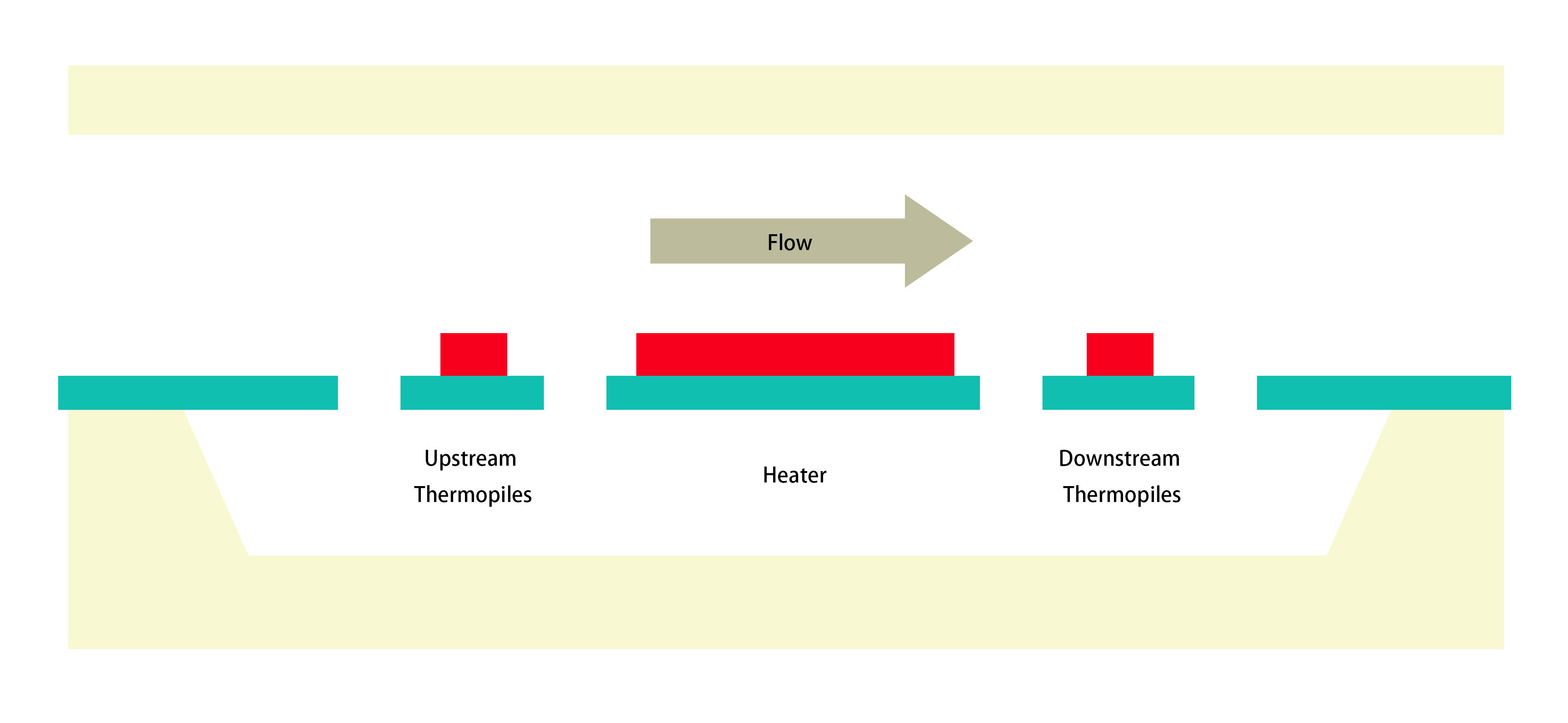
A micromechanical MEMS flow sensor can be made with one or more heaters and temperature sensors. One simple way is to have a heater surrounded by two temperature sensors placed symmetrically at the left and right side. When the heater (actually a resistor) is warmed by passing currents, a steady state temperature profile is built up around the heater. With the symmetry, two temperature sensors detect the same temperature when the gas (media) is not flowing. When the gas is flowing, for example (from left to right), the hot air is blown from left to right, and thus the sensor sees a higher temperature than the temperature sensor at the left side. Since the temperature difference is proportional to the flow rate (linear at low flow rate and non-linear at high flow rate), we can determine the flow rate by measuring the temperature difference of the two temperature sensors.
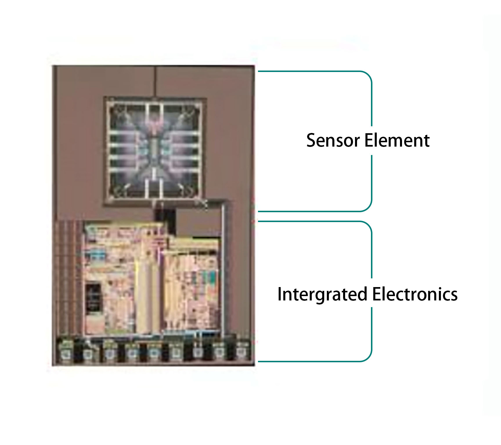
In one implementation of Thermal MEMS flow measurement, the ACEINNA MDP200 sensor, MEMS sensor, and signal conditioning circuit is built together monolithically on a single chip by utilizing standard materials in the CMOS process to build the MEMS flow sensor. In the CMOS process, polysilicon and aluminum are readily available and commonly used for interconnects. In a Thermal MEMS sensor, polysilicon acts as the heater resistor, while the polysilicon and aluminum contact each other to create a thermocouple-based temperature sensor.
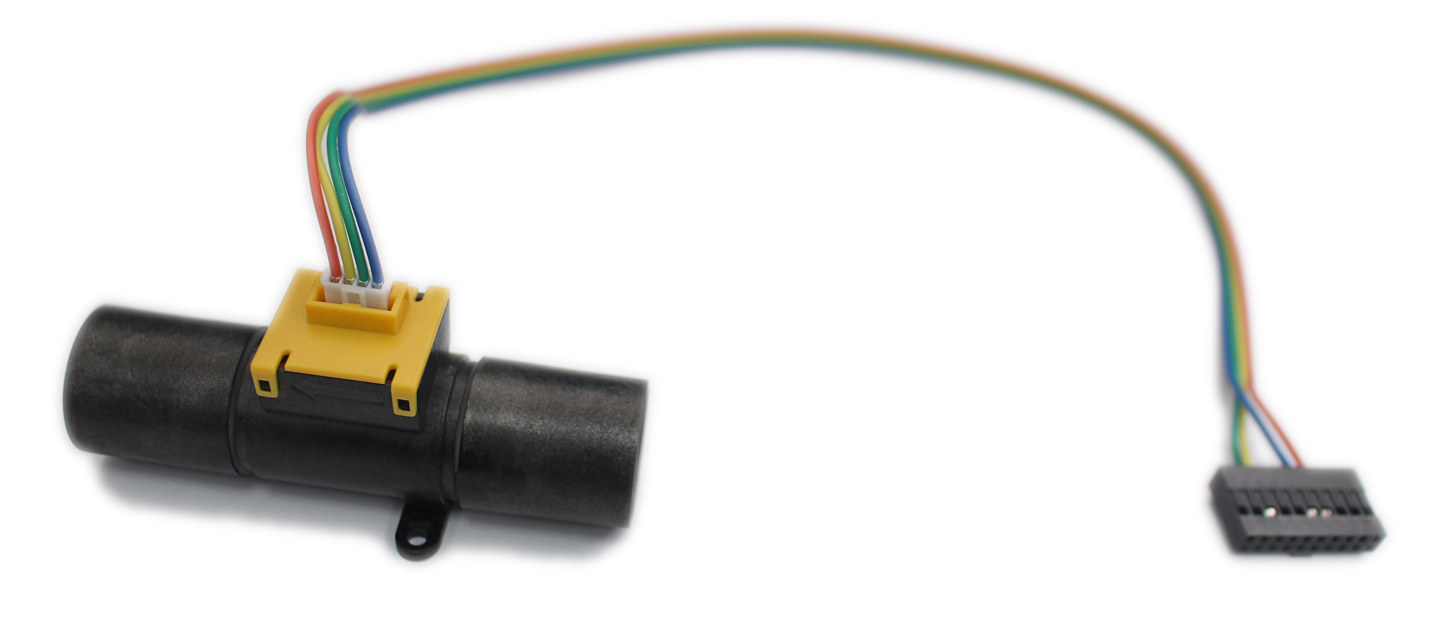
With this modern approach, a MEMS flow sensor can be built without needing any special materials and processes. The signal conditioning circuits can be naturally integrated with the sensor on a single chip. Such monolithic integration enables smaller size, lower cost, higher precision, and control of the sensor. With integrated CMOS circuit, one can monitor the temperature difference down to micro-Kelvin allowing very high resolution and low flow rate sensing. The resulting MDP200 device and its internal sensor is shown below in Figure 2 and Figure 3.
Low-cost semiconductor flow sensors can be simply connected to any standard microcontroller with I2C interface. Software integration can be completed in a couple of hours. Low-power consumption of less than 10 mA at 3.3 V is also generally acceptable. In battery-powered applications, the device can be easily duty-cycled because power-up and measurement time is less than 0.1 second combined.
When selecting and specifying a Thermal MEMS Flow sensor there are a couple more subtle considerations:
- Gas Type
- Accuracy
- Connection Mechanism and Altitude Correction
The gas type must be considered when selecting the gas sensor. Typical gas compatibility includes air, N2, and O2. ACEINNA’s sensor is also compatible with CO2, He, and CH4 (natural gas).
A flow sensor returns a value proportional to flow; hence accuracy is modeled in classic terms with zero-point (offset) and span (linearity) errors.
There are two ways to determine if the accuracy of a flow or differential measurement device is suitable for your requirement. The first and simplest way is to consider the manufacturer’s total accuracy specification. This combines the initial offset and span errors, along with the change in these errors over temperature and other subtle effects.
If this error turns out too large for the intended application, then it is often useful to consider the individual errors separately. In many applications, initial offset error can be removed once the device is installed, reducing the total error budget. In other applications, the required range may be less than the device specification, hence the contribution of span error may also be less than included in the total error specification.
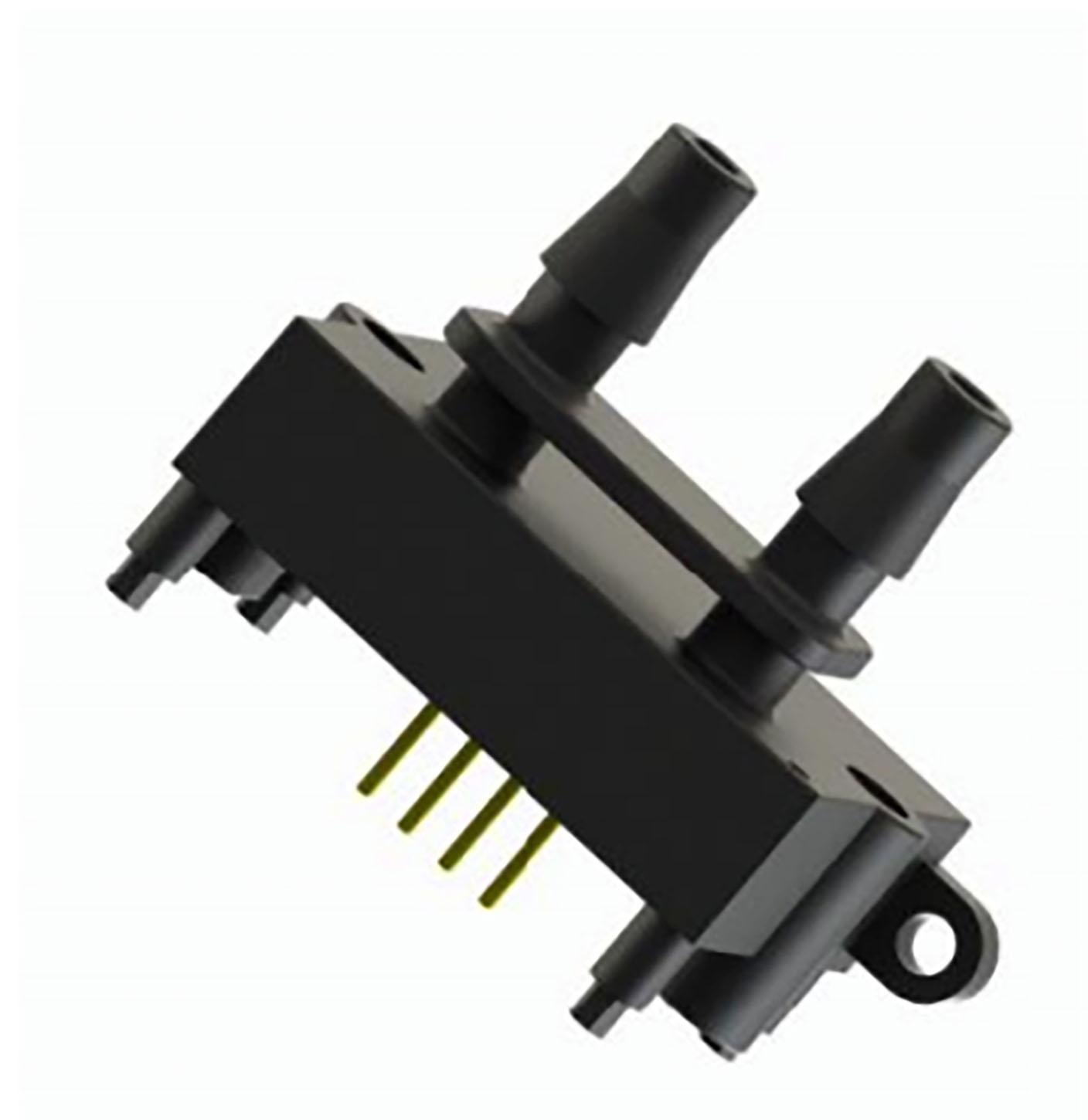
Finally, how to connect the flow sensor into the flow stream is often an interesting challenge. Instead of inserting the device directly in the flow stream, a bypass flow circuit can be used. The Figure 4 diagram below shows how to properly set up a pressure drop circuit, which will force a portion of the flow stream through the device. Such flow drop circuits can be custom made or provided by the flow sensor manufacturer.
Another refined issue is that the DP sensor can require altitude correction for precision applications. Altitude correction is typically accomplished by adding a barometer to the end device. Manufacturers can usually provide an appropriate altitude correction formula. In lower precision applications, this compensation is not required.
