A digital potentiometer (or “digipot”) operates like a traditional mechanical potentiometer (pot), which is a variable resistor, except the digipot is an integrated chip (IC) that accepts signal input rather than the physical movement of a shaft or slide for adjustment. Essentially, both types of potentiometer are analog devices that provide variable resistance. However, a mechanical pot is an adjustable voltage divider by means of an adjustable slider or rotary resistor. Pots physically change the resistance value whereas digipots modify the resistance value via digital inputs rather than a physical slider or rotary wheel. As the shaft of the mechanical pot is turned, the center pin, called a “wiper,” moves and changes the resistance on either site of the wiper.
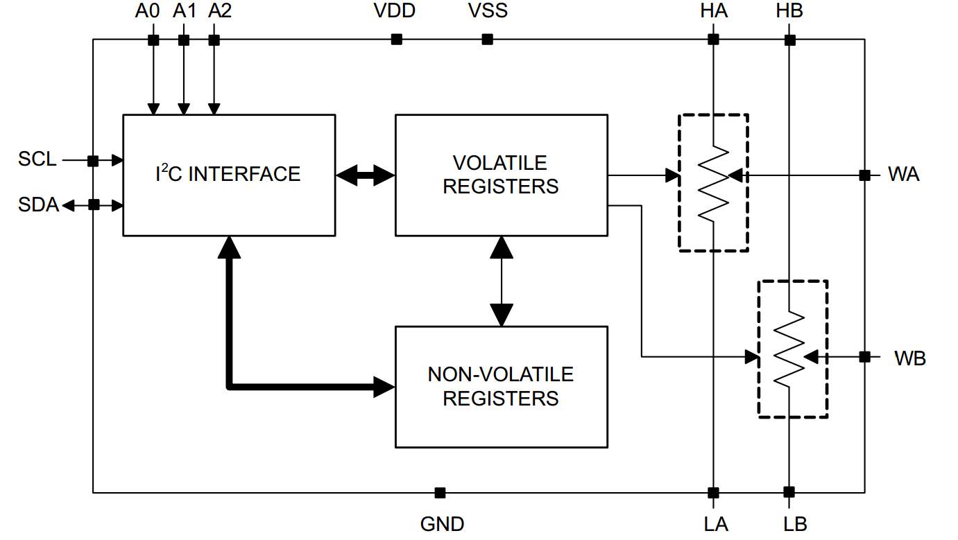
Figure 1: Simplified schematic, or functional block diagram, of a Texas Instruments TPL0102 dual digital potentiometer. (Image Source: ti.com)
Why digital potentiometers?
Digipots are convenient for use where environmental factors can adversely affect a mechanical pot. Environments with vibration or particles like dirt, dust, moisture or grease that can gum up the shaft can drive one to choose a digital potentiometer. Digipots can be better protected from the environment since they can be encapsulated. Digipots are less vulnerable to vibration, less accessible to physical tampering, and can offer more features (being an IC) than a mechanical pot. Additional options for digipots can include a quad-pack of digipots in a single package, shutdown mode, and programmable pre-set positions upon power-on for the wiper. Digipots can use memory (both volatile and non-volatile) for a set wiper position upon start-up. They can eliminate the irritation of mounting a mechanical device to a printed circuit board (PCB), as well. Digital potentiometers are adjusted via writing to the digipot’s digital inputs to set the “wiper,” therefore they do not require physical access.
 Digipots can also offer higher resolution, greater stability, and solid-state reliability. They are smaller than mechanical potentiometers and can fit in tiny IC packages measuring 2.9 mm x 2.8 mm (SOT-23-6) or smaller. On the downside, digipots can be more complicated as they must be programmed, typically with I2C or SPI communication bus protocols. Digital potentiometers can be made with just 1% end-to-end resistance tolerance. The resolution of digital potentiometers has improved to the point that a digipot can replace digital-to-analog converters in some cases. Both DACs and digipots produce an analog output signal in response to a digital input signal. With digital pots, the wiper is the analog output. The important differences, however, are that DACs can have a higher resolution and DACs include an output buffer amplifier, whereas digital pots do not.[i]
Applications
Digital potentiometers can be used where ever mechanical potentiometers are employed,[ii] for sensor trimming and calibration (remote or local), instrumentation (gain or offset adjustment), for adjustable gain amplifiers, audio level control, to match line impedances, in optical networks, for level adjustments in automotive electronics and in programmable power supplies, filters, time constants, or delay values. Another fundamental function of any potentiometer is the ability to use just two of the three terminals, and thus create a rheostat.
[i] “DACs vs. Digital Potentiometers: Which Is Right for My Application?” TUTORIAL 4025. Maxim Integrated, 11 Apr. 2007. Web. 6 Jan. 2017.
[ii] “Digital Potentiometers Replace Mechanical Potentiometers …” Tutorial 3417. Maxim Integrated, 21 Dec. 2004. Web. 6 Jan. 2017.
The post What is a digital potentiometer? appeared first on Analog IC Tips.