• Skip to primary navigation
  • Skip to main content
  • Skip to primary sidebar
  • Skip to footer

Electrical Engineering News and Products

Electronics Engineering Resources, Articles, Forums, Tear Down Videos and Technical Electronics How-To's

  • Products / Components
    • Analog ICs
    • Battery Power
    • Connectors
    • Microcontrollers
    • Power Electronics
    • Sensors
    • Test and Measurement
    • Wire / Cable
  • Applications
    • 5G
    • Automotive/Transportation
    • EV Engineering
    • Industrial
    • IoT
    • Medical
    • Telecommunications
    • Wearables
    • Wireless
  • Learn
    • eBooks / Handbooks
    • EE Training Days
    • Tutorials
    • Learning Center
    • Tech Toolboxes
    • Webinars & Digital Events
  • Resources
    • White Papers
    • Educational Assets
    • Design Guide Library
    • Digital Issues
    • Engineering Diversity & Inclusion
    • LEAP Awards
    • Podcasts
    • DesignFast
  • Videos
    • EE Videos and Interviews
    • Teardown Videos
  • EE Forums
    • EDABoard.com
    • Electro-Tech-Online.com
  • Bill’s Blogs
  • Advertise
  • Subscribe

What is de-embedding and how do I perform it (part 1)?

April 10, 2023 By Rick Nelson

It’s a tenet of the test-and-measurement industry that you should concentrate on looking for defects in your device under test (DUT) — not in your test equipment. Figure 1 illustrates a common problem. An instrument presents an incorrect reading; in this case, an LRC meter or multimeter presents a resistance reading that’s about 5% low. Using four wires is a good start. The extra two wires remove errors in the wires by moving the measurement plane out to the DUT. That’s fine if you’re connecting the DUT directly to your probes without a test fixture. If you need a fixture to hold the DUT, the solution here is to calibrate the instrument-and-fixture combination pre-test — before using it to measure the resistance of any DUTs.

Figure 1. Calibration is a pretest operation that removes a common test-and-measurement error before you begin testing.

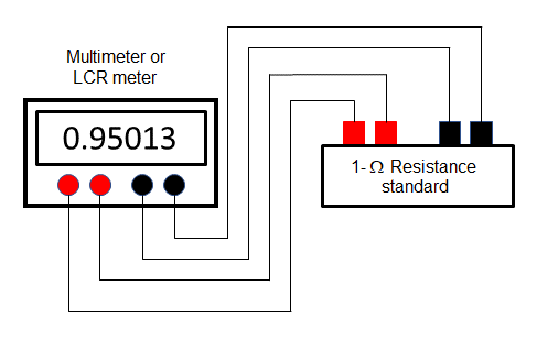
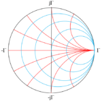
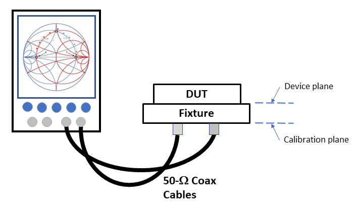
Figure 2 illustrates another problem. You might be using an instrument such as a vector network analyzer (VNA) to measure insertion loss, return loss, or some other parameters. Your VNA probably has a 50-W connector. If your DUT is a millimeter-wave IC, it probably doesn’t. Consequently, you need a test fixture. As a result, your instrument isn’t measuring the DUT — it’s measuring the DUT plus the cables plus the fixture. A standard calibration kit will enable you to extend the calibration plane out to the end of the cables, but not all the way to the device plane, as shown in Figure 2. So even if the VNA is perfectly calibrated, it will give you a precise measurement of the DUT plus the fixture but not of the DUT itself. We need to mathematically remove the characteristics of the fixture from the combined DUT plus fixture measurement. That post-test process is known as de-embedding.

Figure 2. A calibrated VNA can measure the DUT and fixture but not the DUT in isolation.

How can I find the characteristics of the fixture?
You could try to measure the fixture directly with your VNA if you could extend the VNA’s calibration plane to the noncoaxial top of the fixture in Figure 2. But if you could do that conveniently, you probably wouldn’t need the fixture to start with. Typically, engineers use a solver to develop a model based on a detailed description of the fixture, including physical dimensions, materials, and dielectric constants. Companies, including Ansys, CST, Keysight, MathWorks, and NI offer software suites that can create these models or perform calculations based on them.

So, then it’s just a simple subtraction problem, right?
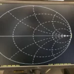
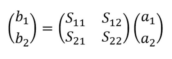
Not quite. The models and VNA measurements will be in terms of scattering parameters (S-parameters), as shown in Figure 3. An S-parameter matrix simply describes how incident waves reflect from or pass through a network.

Figure 3. S-parameter models represent test fixtures and DUTs.

The S-parameters for a two-port network in Figure 3 relate the incident waves a1 and a2 to the reflected and transmitted waves b1 and b2 according to the following matrix equation:

Equation 1.

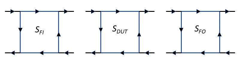
We’ll let SDUT be our shorthand way of representing our DUT’s S-parameter matrix. Now consider the fixture. Since it’s designed to measure a two-port device, it has two sections — let’s call them the input and output sections — represented by the S-parameter matrices SFI and SFO, respectively. It can be helpful to illustrate them as shown in Figure 4.

Figure 4. Three S-parameter matrices represent the fixture input section, the DUT, and the fixture output section.

It looks like we can just wire them up and have a combined S-parameter representation of the DUT and fixture?
If those were gain stages, we could do that — cascade them and multiply the values of each gain stage. That would provide a convenient way to find the gain of the DUT, even if we couldn’t measure it in isolation from the fixture. For example, say we know from models or from direct measurement that the fixture input section has a gain of 2, and the fixture output section has a gain of 1.5. Then, we measure the combined fixture and DUT and find a total gain of 15. Analogous to de-embedding, the gain of the DUT is therefore 15 divided by 2 divided by 1.5, for a DUT gain of 5.

Unfortunately, S-parameters don’t work that way. You’ll note that Equation 1 is not in the form of outputs being a function of inputs from either a left-to-right or right-to-left signal-flow perspective. To extract the characteristics of the DUT from the combined characteristics of the DUT plus fixture, we will need to employ transfer scattering parameters, or T-parameters, which I will discuss in part 2.

Meanwhile, you can learn more about S-parameters here. And if you want to learn more about pretest calibration, fluke calibration has a good introduction.

You Might Also Like

Filed Under: FAQ, Featured, Test and Measurement Tips Tagged With: ansys, CST, keysight, mathworks, ni

Primary Sidebar

EE Engineering Training Days

engineering

Featured Contributions

Integrating MEMS technology into next-gen vehicle safety features

Five challenges for developing next-generation ADAS and autonomous vehicles

Robust design for Variable Frequency Drives and starters

Meeting demand for hidden wearables via Schottky rectifiers

GaN reliability milestones break through the silicon ceiling

More Featured Contributions

EE Tech Toolbox

“ee
Tech Toolbox: 5G Technology
This Tech Toolbox covers the basics of 5G technology plus a story about how engineers designed and built a prototype DSL router mostly from old cellphone parts. Download this first 5G/wired/wireless communications Tech Toolbox to learn more!

EE Learning Center

EE Learning Center
“ee
EXPAND YOUR KNOWLEDGE AND STAY CONNECTED
Get the latest info on technologies, tools and strategies for EE professionals.
“bills
contribute

R&D World Podcasts

R&D 100 Episode 10
See More >

Sponsored Content

Designing for Serviceability: The Role of Interconnects in HVAC Maintenance

From Control Boards to Comfort: How Signal Integrity Drives HVAC Innovation

Built to Withstand: Sealing and Thermal Protection in HVAC Sub-Systems

Revolutionizing Manufacturing with Smart Factories

Smarter HVAC Starts at the Sub-System Level

Empowering aerospace E/E design and innovation through Siemens Xcelerator and Capital in the Cloud

More Sponsored Content >>

RSS Current EDABoard.com discussions

  • Diode recovery test Irrm timing.
  • Battery Deep Discharge – IC Workarounds?
  • The Analog Gods Hate Me
  • Safe Current and Power Density Limits in PCB Copper(in A/m² and W/m³) simulation
  • Why so few Phase shift full bridge controllers?

RSS Current Electro-Tech-Online.com Discussions

  • Wideband matching an electrically short bowtie antenna; 50 ohm, 434 MHz
  • The Analog Gods Hate Me
  • Simple LED Analog Clock Idea
  • PIC KIT 3 not able to program dsPIC
  • Parts required for a personal project
Search Millions of Parts from Thousands of Suppliers.

Search Now!
design fast globle

Footer

EE World Online

EE WORLD ONLINE NETWORK

  • 5G Technology World
  • Analog IC Tips
  • Battery Power Tips
  • Connector Tips
  • DesignFast
  • EDABoard Forums
  • Electro-Tech-Online Forums
  • Engineer's Garage
  • EV Engineering
  • Microcontroller Tips
  • Power Electronic Tips
  • Sensor Tips
  • Test and Measurement Tips

EE WORLD ONLINE

  • Subscribe to our newsletter
  • Teardown Videos
  • Advertise with us
  • Contact us
  • About Us

Copyright © 2025 · WTWH Media LLC and its licensors. All rights reserved.
The material on this site may not be reproduced, distributed, transmitted, cached or otherwise used, except with the prior written permission of WTWH Media.

Privacy Policy