• Skip to primary navigation
  • Skip to main content
  • Skip to primary sidebar
  • Skip to footer

Electrical Engineering News and Products

Electronics Engineering Resources, Articles, Forums, Tear Down Videos and Technical Electronics How-To's

  • Products / Components
    • Analog ICs
    • Battery Power
    • Connectors
    • Microcontrollers
    • Power Electronics
    • Sensors
    • Test and Measurement
    • Wire / Cable
  • Applications
    • 5G
    • Automotive/Transportation
    • EV Engineering
    • Industrial
    • IoT
    • Medical
    • Telecommunications
    • Wearables
    • Wireless
  • Learn
    • eBooks / Handbooks
    • EE Training Days
    • Tutorials
    • Learning Center
    • Tech Toolboxes
    • Webinars & Digital Events
  • Resources
    • White Papers
    • Educational Assets
    • Design Guide Library
    • Digital Issues
    • Engineering Diversity & Inclusion
    • LEAP Awards
    • Podcasts
    • DesignFast
  • Videos
    • EE Videos and Interviews
    • Teardown Videos
  • EE Forums
    • EDABoard.com
    • Electro-Tech-Online.com
  • Bill’s Blogs
  • Advertise
  • Subscribe

What is de-embedding and how do I perform it (part 2)?

May 15, 2023 By Rick Nelson

When testing a device in a fixture, you can use transfer scattering parameters (T-parameters) to help remove the fixture’s contribution from your measurement result.

When measuring a device under test, it’s often convenient or necessary to use a fixture — for example, when your instrument has a coaxial connector and your DUT does not. As described in part 1 of this two-part series, after your measurement is complete, you will need to remove the behavior of the fixture from the total measured result to get an accurate measurement of the DUT alone.

You mentioned in part 1 that our two-port DUT requires a fixture with two sections, right?
Right. We called them the input and output sections. Figure 1 shows flow diagrams of the two sections of the fixture as well as the DUT along with their S-parameter matrices (SFI and SFO for the fixture input and output sections, respectively, and SDUT for the DUT). We have S-parameter matrices of the fixture sections from models, as described in part 1. Then, use a vector network analyzer (VNA) to measure the S-parameters of the combined fixture and DUT, which we will label SFI+DUT+FO. At this point, the only unknown is SDUT.
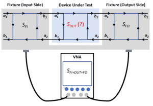
S-parameters for text fixture with VNA
Figure 1. A vector network analyzer measures S-parameters for a test-fixture and DUT combination.

OK, so can we just divide SFI+DUT+FO by SFI and SFO to get SDUT?
If the DUT and fixture blocks in Figure 1 were simple gain stages, then we could do that. If the total measured gain is 5 and we know the fixture input and output sections have gains of 0.75 and 0.8, then the DUT gain is 5 divided by 0.75 divided by 0.8 equals 8.33. Unfortunately, S-parameters don’t work that way.

Why not?
Figure 2, which shows an S-parameter flow diagram and the S-parameter equation, provides an intuitive picture of the problem. The equation expresses the scattered signals (the reflected and transmitted signals) b1 and b2 as functions of the incident signals a1 and a2. Because we have a and b signals at both ends of the network, we don’t have a traditional signal-flow representation of inputs and outputs that would allow us to cascade multiple two-port networks to obtain a larger two-port network — or more to the point for de-embedding, take a cascaded network and separate out the parts representing the fixture.

S-parameter representation
Figure 2. In an S-parameter representation, a and b parameters appear at each port.

What’s the solution?
We need a representation that gives us a more traditional input/output signal-flow, with a1 and b1 on one side of the equation and a2 and b2 on the other:

Fortunately, transfer scattering parameters, or T-parameters, can fill in for the question marks. Here’s the equation for a two-port T-parameter matrix:

You can perform some matrix algebra on the S-parameter and T-parameter equations to find the values of the individual T-parameters in terms of the individual S-parameters, as shown in Figure 3.

eliminate T--parameters
Figure 3. If you know the S-parameters, you can calculate the T-parameters.

We can now convert SFI+DUT+FO, SFI, and SFO to their T-parameter equivalents, as shown in Figure 4, where TDUT remains unknown.

So how do we get to the de-embedded DUT measurement?
Now we can use division, as you suggested earlier. We can separate out the TDUT matrix from the TFI+DUT+FO matrix by dividing TFI+DUT+FO by SFI, and SFO¬. With matrix algebra, division is best accomplished by multiplying by the inverses of the matrices in the denominator:
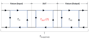
Figure 4. T-parameters represent the test fixture and measured SFI+DUT+FO, while TDUT remains unknown.

As the final step, we convert TDUT to the desired S-parameter matrix SDUT using the equations in Figure 5, the converse of the equations in Figure 4.

It looks like a lot of matrix algebra, doesn’t it?
Your best bet is to choose a VNA that lets you upload your fixture S-parameter files and then does the calculations for you. Keep in mind that calibration is an inconvenient pre-test process, which may require returning your instrument to the manufacturer or to an independent calibration lab. De-embedding is a post-test process, but many VNAs can do the post-test processing and deliver results in near real time.

Is there an embedding alternative to de-embedding?
Indeed, there is. In some cases, a DUT test involves tuning of some sort. Such a DUT tuned in isolation may require further retuning when it’s integrated into a system with other components. An embedding technique during the initial test — involving S-parameter models of the as-yet unavailable other components — can minimize the need for subsequent retuning at the system level.

Figure 5. The final step in the de-embedding process is to convert the DUT’s T-parameters to S-parameters using these equations.

Where can I learn more?
Keysight has an application note on de-embedding, with details on converting S-parameters to T-parameters, and vice versa. Rohde & Schwarz has an application note that covers test-fixture characterization and de-embedding for a PCIe connector and other applications. Anritsu comments on how Higher data rates are requiring new de-embedding techniques.

You Might Also Like

Filed Under: FAQ, Featured, Test and Measurement Tips Tagged With: anritsu, anritsucompany, keysight, keysighttechnologies, rohdeschwarz

Primary Sidebar

EE Engineering Training Days

engineering

Featured Contributions

Five challenges for developing next-generation ADAS and autonomous vehicles

Robust design for Variable Frequency Drives and starters

Meeting demand for hidden wearables via Schottky rectifiers

GaN reliability milestones break through the silicon ceiling

From extreme to mainstream: how industrial connectors are evolving to meet today’s harsh demands

More Featured Contributions

EE Tech Toolbox

“ee
Tech Toolbox: 5G Technology
This Tech Toolbox covers the basics of 5G technology plus a story about how engineers designed and built a prototype DSL router mostly from old cellphone parts. Download this first 5G/wired/wireless communications Tech Toolbox to learn more!

EE Learning Center

EE Learning Center
“ee
EXPAND YOUR KNOWLEDGE AND STAY CONNECTED
Get the latest info on technologies, tools and strategies for EE professionals.
“bills
contribute

R&D World Podcasts

R&D 100 Episode 10
See More >

Sponsored Content

Advanced Embedded Systems Debug with Jitter and Real-Time Eye Analysis

Connectors Enabling the Evolution of AR/VR/MR Devices

Award-Winning Thermal Management for 5G Designs

Making Rugged and Reliable Connections

Omron’s systematic approach to a better PCB connector

Looking for an Excellent Resource on RF & Microwave Power Measurements? Read This eBook

More Sponsored Content >>

RSS Current EDABoard.com discussions

  • How to simulate a microstrip gap with such a reference plane
  • Phase Shift Full Bridge suffers spurious FET turn_ON
  • optimum spacing between feed and sub reflector
  • Equipment to see if household should buy battery/solar/inverter?
  • 'HERIC' pairs of IGBTs essential for Mains inverters

RSS Current Electro-Tech-Online.com Discussions

  • Adhesive Defibrillator Pad Cable
  • Epson crystal oscillators
  • Simple LED Analog Clock Idea
  • Fun with AI and swordfish basic
  • Microinverters and storeage batteries?
Search Millions of Parts from Thousands of Suppliers.

Search Now!
design fast globle

Footer

EE World Online

EE WORLD ONLINE NETWORK

  • 5G Technology World
  • Analog IC Tips
  • Battery Power Tips
  • Connector Tips
  • DesignFast
  • EDABoard Forums
  • Electro-Tech-Online Forums
  • Engineer's Garage
  • EV Engineering
  • Microcontroller Tips
  • Power Electronic Tips
  • Sensor Tips
  • Test and Measurement Tips

EE WORLD ONLINE

  • Subscribe to our newsletter
  • Teardown Videos
  • Advertise with us
  • Contact us
  • About Us

Copyright © 2025 · WTWH Media LLC and its licensors. All rights reserved.
The material on this site may not be reproduced, distributed, transmitted, cached or otherwise used, except with the prior written permission of WTWH Media.

Privacy Policy