There are many parameters which define the performance of analog and mixed-signal circuits. Among the many “static” (sometimes called “DC” specifications, but this is a misnomer) factors are offset error, gain error, integral nonlinearity, and differential nonlinearity. Note that there are also dynamic specifications (called “AC” specifications but also a misnomer) such as the effective number of bits (ENOB), signal to noise ratio (SNR), and spur-free dynamic range (SFDR).
Although these parameters can be associated with the entire analog channel or with any subsection of it, they are more closely connected to the analog/digital and digital/analog converters. The reason is that these converters are the transitional interface between analog and digital domains, and are thus the most likely to have deviations and errors that all-analog circuit would not have.
Q: What is “monotonic” in this context?
There is also another specification associated with mixed-signal and analog circuits: monotonic performance and monotonicity. Unlike the other parameters which characterize component imperfections, and which are characterized by a numerical specification such as integral nonlinearity of ±0.5 LSB, monotonicity is a “yes or no” attribute.
Q: What does monotonic mean?
It means that the input/output transfer function of a converter (or other component, or of the overall channel) may be imperfect, but the curve never reverses direction. A monolithic converter is one where the output increases with increases in input, and never decreases (and vice versa). Mathematically, it means that the derivative of the transfer function never changes sign.
Q: What is a non-monotonic converter?
In a non-monotonic converter, this “same direction” correspondence between input and output direction reverses at one or more points of the transfer curve, Figure 1. In terms of specifications, it means that the differential nonlinearity (DNL) is more positive than 1 LSB. Also, if the DNL > 1 LSB, the A/D converter may also have “missing codes,” meaning that some digital output values never appear, although they should.
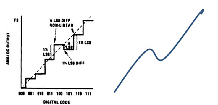
Fig 1: In a non-monotonic converter, the differential nonlinearity is greater than 1, and the converter output may decrease (or increase) when the input increases (or decreases), leading to serious closed-loop control problems. (Image source: Linear Applications Handbook, National Semiconductor Corp.)
Q: Why is monotonicity important, compared to the other specifications?
The other specifications tell you how good the converter is, but you can have a fairly good converter which is nonetheless not monotonic. While guaranteed monotonicity is important in test and measurement (instrumentation) applications, it is especially important in closed-loop control situations. For this reason, many converters are guaranteed to be monotonic by their vendors, in addition to the detailed specifications.
Q: Why is this so?
An example will show why it is important. Consider a closed-loop system used to steer a ship, and let’s say that when the rudder-control wheel is at +10° port, the rudder is also at the same setting; in other words, the angle of the wheel and the rudder are always supposed to be the same. Suppose the captain says, “give me another +5° rudder to port.” If the converter is less-than-perfect, the rudder may only turn 3°, or it may turn 6°, but in either case, it does increase in angle.
However, in a non-monotonic situation, the wheel is turned that extra 5° to port, but instead goes towards starboard, from its initial setting of 10° down to 8°. In other words, the direction of the response – defined by the transfer function – is the opposite of what was intended, which is worse than just “not quite right.” That can cause serious control problems.
It’s not just ships that could be adversely affected by non-monotonic behavior. The same concerns apply to accelerating a car, where depressing the accelerator to go faster would result in the car actually going slower at some angles of the pedal, or a heating system where a call for more heat would bring less heat, or reactor control rods where an instruction to lower them would cause them to instead rise at some settings.
Q: Can non-monotonic behavior be calibrated or compensated?
Yes and no. In theory, a detailed input/output transfer function could be established for a given converter or channel. Then, any input or command would be adjusted based on the calibration. But this is time-consuming, impractical, and would cause problems if a component was replaced. In practice, it is not a desirable or practical solution.
Q: Are all converter implementations at risk of being non-monotonic?
No. Some architectures use techniques such as pulse counting or accumulating charge, and these are inherently monotonic topologies. Note that non-monotonic converters and components, whether due to inferior processes or test phases, are available for those few applications for which it is not a critical factor.
Q: What is the solution, if there are monoticity concerns?
Nearly all lower-resolution converters (8 to 12/14 bits) are monotonic, and most higher-resolution ones (>14 bits) are monotonic as well. In these parts, monoticity is assured by the vendor via careful component design, test, and trim processes. If monoticity is important (it is in many, but not all applications), then designers should specify parts which are “guaranteed monotonic” by topology or credible vendor data sheet.
Reference
Texas Instruments Application Report SLAA013, “Understanding Data Converters”


Leave a Reply
You must be logged in to post a comment.