• Skip to primary navigation
  • Skip to main content
  • Skip to primary sidebar
  • Skip to footer

Electrical Engineering News and Products

Electronics Engineering Resources, Articles, Forums, Tear Down Videos and Technical Electronics How-To's

  • Products / Components
    • Analog ICs
    • Connectors
    • Microcontrollers
    • Power Electronics
    • Sensors
    • Test and Measurement
    • Wire / Cable
  • Applications
    • Automotive/Transportation
    • Industrial
    • IoT
    • Medical
    • Telecommunications
    • Wearables
    • Wireless
  • Resources
    • DesignFast
    • Digital Issues
    • Engineering Week
    • Oscilloscope Product Finder
    • Podcasts
    • Webinars / Digital Events
    • White Papers
    • Women in Engineering
  • Videos
    • Teschler’s Teardown Videos
    • EE Videos and Interviews
  • Learning Center
    • EE Classrooms
    • Design Guides
      • WiFi & the IOT Design Guide
      • Microcontrollers Design Guide
      • State of the Art Inductors Design Guide
    • FAQs
    • Ebooks / Tech Tips
  • EE Forums
    • EDABoard.com
    • Electro-Tech-Online.com
  • 5G

What is the common impedance of a twisted pair?

May 10, 2022 By Martin Rowe

Understanding impedance in twisted-pair cables help you avoid signal problems.

A twisted pair, such as what you would find in Ethernet cables, is designed to economically transport a differential signal. It is a differential-pair interconnect, even though there are only two conductors. How do we make sense of this interconnect, especially when we want to think about its common impedance?

The secret to understanding the properties of a twisted pair as a differential interconnect is to identify the third conductor: ground. In this context, I don’t mean electrical ground. I mean ground, as in the floor.

Twisted pairs are common in communications cables such as Ethernet and serial ports.

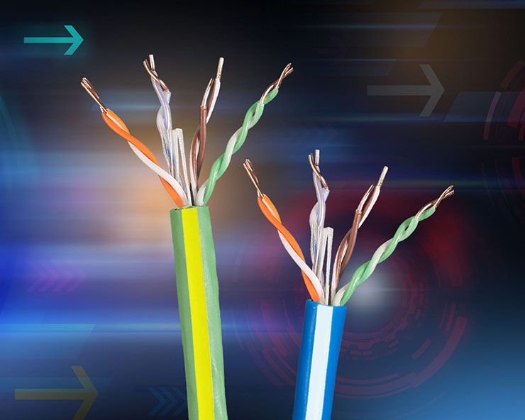
Every differential pair is composed of two single-ended transmission lines — no exceptions. Each of the two single-ended transmission lines in a twisted pair is really composed of a signal line (one of the wires in the pair) and its return path. In unshielded twisted pair cable, like Cat5 cable, the return path is a complicated structure composed of the fringe fields to the chassis, to the adjacent wires in the cable, and to any nearby conducting surface, which is usually the ground, as in the floor. This will vary as the cable is moved and the proximity to the floor or nearby metal changes.

The single-ended properties of each transmission line in a twisted pair are terrible. This is not very controlled impedance. The single-ended impedance of the cable varies down its length, depending on the position of the local conductors.

When we launch a differential signal down the two transmission lines, it is really composed of two single-ended signals propagating in the same direction. One is a positive voltage, and the other is a negative voltage. The return currents of these single-ended signals travel over a complicated and convoluted path, but generally they follow the same path. They cancel each other out because they circulate in opposite directions.

The more the return currents of the single-ended transmission lines overlap and cancel out, the less influence the convoluted return path has on the differential signal. Therefore, a twisted pair provides a very clean, uniform differential impedance.

The common signal is different. A common signal is the same voltage on both lines. The return currents of these two transmission lines overlap, but as the return currents of a common signal circulate in the same direction, they just add in the return path.

The common-impedance profile will show the impedance variation due to that convoluted return path, and it will generally be very high impedance.

The plot below shows an example of the measured differential and common impedance profile for a twisted pair, taken out of a Cat5 cable and spread over a table top.

This impedance profile shows how differential impedance can stay flat over frequency while common-mode impedance can vary.

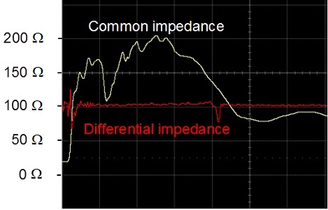
The typical common impedance of an unshielded twisted pair will vary from around 100 Ω to 200 Ω. As long as there are no common signals on the twisted pair, you don’t need to care about the common impedance. The challenge is preventing common signals from getting on the twisted pair.

You may also like:


  • How to keep transients from disrupting low-power circuits

  • How does Cat 5e cable handle Hi PoE?

  • Attenuation networks and their measurement

  • Single-Pair Ethernet addresses industrial priorities, Part 2: Hardware realization

  • Single-Pair Ethernet addresses industrial priorities, Part 1: The IEEE 802.3cg…
DesignFast Banner version: a237563e

Filed Under: Connector Tips, FAQ, Featured

Primary Sidebar

EE Training Center Classrooms

“ee

“ee

“ee

“ee

“ee

“ee

Featured Resources

  • EE World Online Learning Center
  • CUI Devices – CUI Insights Blog
  • EE Classroom: Power Delivery
  • EE Classroom: Building Automation
  • EE Classroom: Aerospace & Defense
  • EE Classroom: Grid Infrastructure
Search Millions of Parts from Thousands of Suppliers.

Search Now!
design fast globle

R&D World Podcasts

R&D 100 Episode 7
See More >

Current Digital Issue

February 2022 Special Edition: Power Electronics Handbook

Up in the sky! It’s a bird! It’s a plane! It’s a flying battery! According to a company called Joby Aviation, in a few years you’ll be able to summon up an air taxi on your Uber phone app for trips of 25 miles or so. And you won’t have to feel guilty about the…

Digital Edition Back Issues

Sponsored Content

Positioning in 5G NR – A look at the technology and related test aspects

Radar, NFC, UV Sensors, and Weather Kits are Some of the New RAKwireless Products for IoT

5G Connectors: Enabling the global 5G vision

Control EMI with I-PEX ZenShield™ Connectors

Speed-up time-to-tapeout with the Aprisa digital place-and-route system and Solido Characterization Suite

Siemens Analogue IC Design Simulation Flow

More Sponsored Content >>

RSS Current EDABoard.com discussions

  • I am Alec, a new member!
  • electrode-skin impedance mismatch
  • how to estimate Senseamp offset voltage to use montecarlo ?
  • Weird transformer result in ads
  • could calibre lvs do not check mosfet B term

RSS Current Electro-Tech-Online.com Discussions

  • Relaxation oscillator with neon or...
  • High component count for long delay circuit (inrush resistor switch out)
  • DIY Mini 12v Router UPS malfunction
  • MOSFET gets hot and burns
  • Positive and negative sides of voltage source

Oscilloscopes Product Finder

Footer

EE World Online

EE WORLD ONLINE NETWORK

  • 5G Technology World
  • Analog IC Tips
  • Battery Power Tips
  • Connector Tips
  • DesignFast
  • EDABoard Forums
  • Electro-Tech-Online Forums
  • Engineer's Garage
  • Microcontroller Tips
  • Power Electronic Tips
  • Sensor Tips
  • Test and Measurement Tips
  • Wire & Cable Tips

EE WORLD ONLINE

  • Subscribe to our newsletter
  • Lee's teardown videos
  • Advertise with us
  • Contact us
  • About Us
Follow us on TwitterAdd us on FacebookConnect with us on LinkedIn Follow us on YouTube Add us on Instagram

Copyright © 2022 · WTWH Media LLC and its licensors. All rights reserved.
The material on this site may not be reproduced, distributed, transmitted, cached or otherwise used, except with the prior written permission of WTWH Media.

Privacy Policy