FlexRay is an ISO-standardized, deterministic, fault-tolerant, high-speed communications bus with applications in steer-by-wire, drive-by-wire, brake-by-wire, adaptive cruise control, active suspension, and other safety and drivetrain control systems.
This FAQ offers a top-level comparison of FlexRay with the controller area network (CAN) and local interconnect network (LIN) buses, details the FlexRay communications cycle, and reviews FlexRay network topologies and applications.
FlexRay competes with flexible data-rate CAN (CAN FD) and high-speed CAN (HS-CAN) in time-critical applications but not with regular CAN or LIN buses (Table 1).
The features of FlexRay include:
- Bit rates of up to 10 Mbps with half-duplex bus access
- ISO standard 17458
- Supports fault-tolerant mechanisms
- Support for time-triggered and event-triggered modes
- Implemented in a variety of single and dual-channel topologies
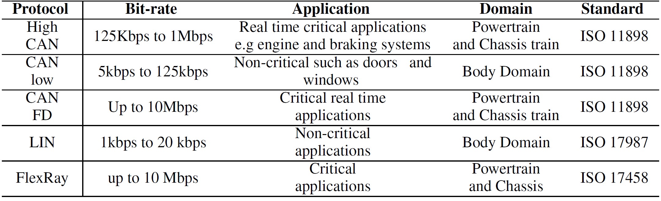
In terms of cost, LIN is the least expensive per node compared to CAN and FlexRay. The high-performance FlexRay bus is the most costly, with CAN falling between the two.
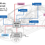
FlexRay is the newest of these three communication buses and was developed by the automotive industry to address the need for rapid, redundant, and deterministic high-speed communications for ADAS and other advanced automotive systems.
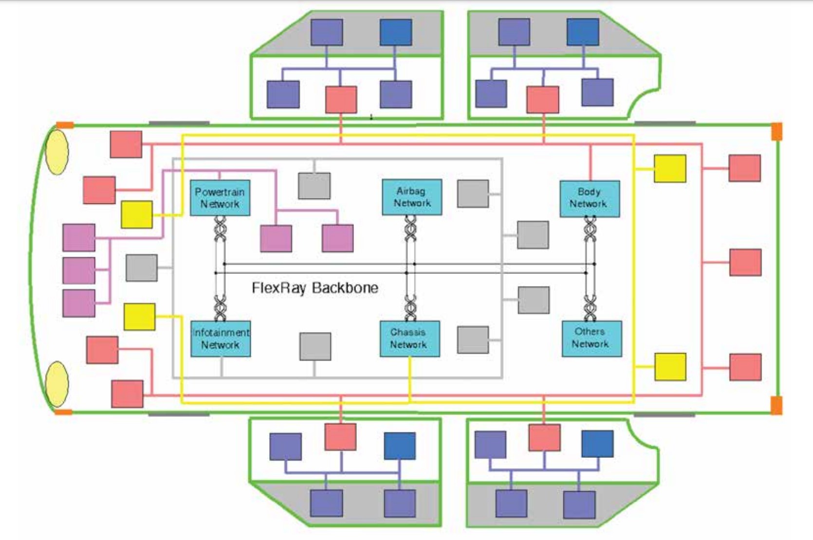
A FlexRay network can operate up to 20 times faster than the maximum CAN data-rate specification. In addition to supporting safety-related and real-time applications, a FlexRay bus can be used as a communications backbone for connecting heterogeneous networks throughout an automobile (Figure 1).
Although FlexRay is the most expensive of the three buses, several aspects of its design are intended to help control costs. For example, it uses inexpensive unshielded twisted pair (UTP) cabling and differential signaling on each pair of wires to reduce the effects of external noise on the network. Single and dual-channel FlexRay networks use one or two pairs of wires.
In addition, most nodes include power and ground wires to power transceivers, microprocessors, and other system components. Dual-channel FlexRay networks also offer higher levels of fault tolerance and/or higher bandwidths.
Termination resistors between 80 and 110 Ω are required on the ends of FlexRay buses and between the two signal wires. In a multi-drop bus, only the end nodes need termination. Incorrect values of termination resistors are a common source of poor performance in FlexRay networks.
Since specific network implementations vary, the cabling impedance differs (usually between 80 and 110 Ω), making it essential to identify and use the correct termination resistor value. Also, because FlexRay operates at higher frequencies (10 Mbit/s) compared to CAN (1 Mbit/s), it’s important to terminate and layout FlexRay networks correctly to avoid signal integrity issues.
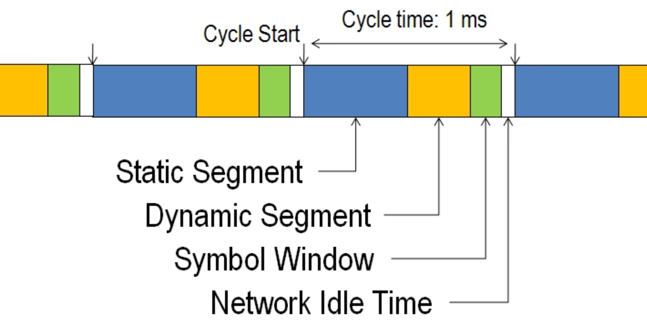
FlexRay communication cycle
A FlexRay communication cycle’s duration can vary between 1 to 5 milliseconds (ms) and is set when the network is designed. The communication cycle has four primary elements (Figure 2):
- Static segment – reserved slots for deterministic data arriving at a fixed period
- Dynamic segment – used for non-deterministic event-based data
- Symbol window – used for network maintenance and signaling when starting the network
- Network idle time – A fixed “quiet” time to maintain synchronization between node clocks
A microtick is the smallest unit of time used on a FlexRay network. Like the communications cycle, the length of a microtick can vary between networks, but it’s typically one microsecond (μs) long. FlexRay controllers adjust their local clocks so that the microtick occurs simultaneously at every node across the network. The microtick is also used to synchronize data and enable deterministic operation.
FlexRay topology
FlexRay offers more topology choices than CAN, LIN, or automotive Ethernet. It supports multi-drop passive connections, active star connections, and hybrid topologies for more complex networks. The variety of FlexRay topologies helps designers optimize the tradeoffs between cost, performance, and reliability in the overall vehicle architecture.
Multi-drop
The most common FlexRay is a multi-drop topology with a single network cable connecting multiple ECUs. CAN and LIN are also based on a multi-drop topology, making this design familiar and easy to implement. Individual ECUs can be located a small distance from the main FlexRay bus. This topology simplifies installation since it’s easily integrated into existing wiring harnesses designed to support CAN and LIN networks.
Star
FlexRay also supports star topologies where multiple ECUs are connected to a central controller or active node. Using a star topology can make it possible to operate FlexRay networks over longer distances. It also supports network segmentation to improve robustness and reliability if a portion of the network fails. If one of the star branches is cut or shorted, the others continue to function. Additionally, shorter cabling segments reduce the chance of noise coupling on any given segment, increasing immunity to electromagnetic interference (EMI).
Hybrid
FlexRay also supports hybrid combinations of multi-drop and star topologies. This enables the design of an automobile that benefits from the relative simplicity and low cost of a conventional multi-drop topology while using a reliable star configuration to support advanced ADAS features.
FlexRay protocol
The FlexRay protocol includes deterministic, time-triggered communications and dynamic event-driven communication to handle several frames. This is implemented via a pre-set communication cycle with pre-defined spaces for static and dynamic data. The result is a complex but more capable network.
For example, a CAN node only needs the baud rate to communicate, whereas the nodes on a FlexRay network must “understand” how all the nodes of the network are configured before communicating with them.
To prevent bus contention, where multiple nodes try to communicate at the same time, FlexRay uses time-division multiple-access (TDMA) technology. For TDMA to be effective, every node in a FlexRay network must be synchronized to a common clock. Each node has an assigned time slot for communicating with the network. TDMA ensures the consistent timing needed to provide deterministic communications.
Configuring a TDMA network like FlexRay is more complicated than installing a CAN or LIN network. Designers have several tools available to implement FlexRay and optimize the tradeoffs between the network update speeds, deterministic data volume, dynamic data volume, and other parameters. As a result, every FlexRay network is different. Each node must be programmed with detailed network parameters before operation.
The performance advantages of FlexRay are expected to increase its longevity. While CAN and LIN buses are being replaced in many applications by automotive Ethernet, FlexRay is expected to continue to be used in safety-critical applications for the foreseeable future.
Summary
FlexRay offers several advantages over other automotive buses such as CAN, LIN, and Ethernet — providing deterministic, high-speed communication required by safety-critical ADAS systems.
FlexRay is costlier than CAN and LIN buses but offers several configuration and performance options unavailable with the other buses. These configurations mean FlexRay is more flexible and complex to implement, offering superior performance overall.
FlexRay is expected to gain a guaranteed spot in automotive bus architectures even after many CAN and LIN buses have been replaced with Ethernet.
References
- Cyberattacks and Countermeasures for In-Vehicle Networks, ResearchGate
- FlexRay, Wikipedia
- FlexRay Automotive Communication Bus Overview, NI
- In-Vehicle Network Design, Synopsys