Connectors for electric vehicle (EV) charging are both standardized and changing. On one level, EV charging connectors are standardized based on today’s technology limitations. There are standards in major regional markets, including North America, Japan, the European Union, and China. But current charging technologies are power limited. This FAQ begins with a review of EV charger connector standardization status, followed by a look at liquid-cooled connectors for higher-power and faster-charging technologies. It closes with a glance at emerging MW-level high-voltage charging, wireless charging, and opportunity charging technologies and connectors for heavy-duty vehicles like Class 8 trucks and buses and the potential impact those developments will have on automotive EV charging.
The standards for EV charging connectors are narrowing somewhat. For AC charging, the SAE J1772 Type 1 connector is used in North America and Japan, the IEC 62196 type 2 (also called the Mennekes) connector is used in Europe, and a version of the GB/T connector is used in China. In North America and Europe, variations on the Combined Charging System (CCS) have been adopted for DC charging. CHAdeMO is the Japanese standard, and GB/T is used in China (Figure 1). In addition, there are regional differences in the available power levels related to differences in mains voltages.
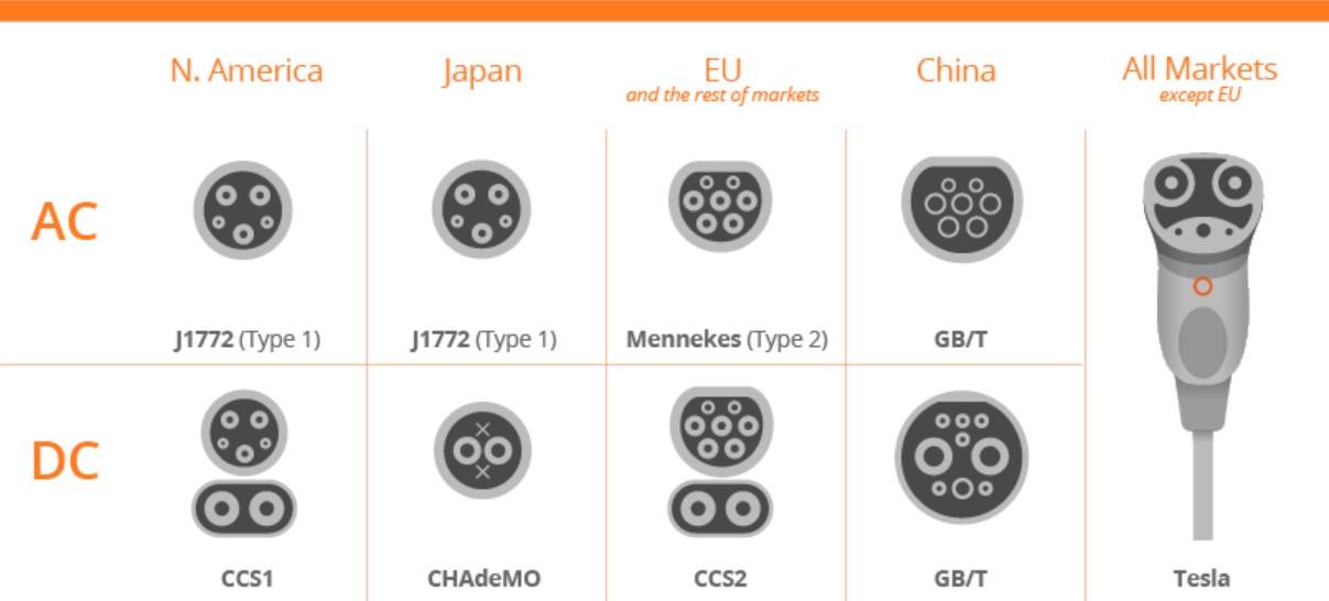
Every EV sold in North America can use charging stations with J1772 connectors. Except for Tesla, all EVs use the J1772 for Level 1 (120V) and Level 2 (240V) charging. Tesla owners receive an adapter cable to connect their EVs to charging stations with J1772 connectors.
Since residences in Europe do not have 120V service, Level 1 charging is not used. And instead of the J1772, the IEC 62196 type 2 connector is used for Level 2 AC charging. Tesla is once again the exception and uses a proprietary connector for most of its EVs. However, a few Tesla models use the IEC 62196 type 2 connector. In both Europe and North America, Tesla’s Level 1 and Level 2 chargers use a proprietary connector, and an adapter is required for EVs from other makers.
DC fast charge connectors
Current DC fast chargers use 480 V mains power for faster charging. That input voltage level is expected to rise in the future as higher-power and faster-charging technologies become available. In North America, the CCS type 1 connector ‘combines’ the J1772 connector adds two high-speed charging pins below. In Europe, CCS combines the IEC 62196 type 2 with two high-speed charging pins and is called the CCS type 2.
The CharIN (Charging Interface Initiative) association is headquartered in Germany and began with the objective to establish CCS as the global standard for EV DC fast charging. CharIN has over 250 members and is working to develop new technologies and extend its reach into MW charging systems for large vehicles like Class 8 trucks, e-ferries, ships, and planes.
CHAdeMo was developed by the Tokyo Electric Power Company (Tepco) and is used across Japan for EV DC fast charging. In contrast with the CCS system, CHAdeMO connectors do not share part of the connector with the J1772 inlet. Since CHAdeMO is strictly for DC fast charging, EVs using that connector also include a separate J1772 inlet for AC Level 1 and Level 2 charging, requiring a larger charge port area to accommodate two separate charging inlets.
Tesla is the exception to the above discussion. Its vehicles use the same proprietary connector for level 1, level 2, and DC fast charge. The Tesla EV charging connector accepts all voltages. Non-Tesla vehicles can use Tesla Level 1 and Level 2 AC chargers with the appropriate adapter connector. Only Tesla vehicles can use the company’s Supercharger DC fast-charging stations. The Supercharger stations use an authentication process to ensure that only Tesla vehicles can be charged. Even with an adapter, it is not possible to charge non-Tesla EVs at Tesla Supercharger DC fast-charging stations.
Liquid-cooled connectors and connectors
DC extreme fast charging (XFC) is an emerging technology for rapid EV charging with 350kW or more. That’s great, but it comes with challenges, including effective thermal management. DC fast chargers rely on larger conductors to help minimize IR losses and heat generation. If not properly designed, the cables and connectors can get bulky and hot and be difficult to handle.
Liquid cooling is increasingly being offered as a solution to unlock the higher performance and shorter charging times promised by XFC technology. Liquid-cooled cables enable smaller conductors to handle 500A of current and reduce cable weight by about 40%. The smaller cables can fit into existing CCS connector systems (Figure 2). In addition, lighter-weight cables are easier to handle, promoting safe and reliable operation when used with consumer EVs and light trucks.
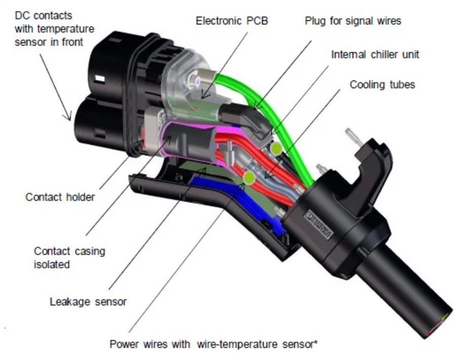
Figure 2: Example of liquid-cooled connector for 475kW DC EV ultra-fast charging (Image: Gilbarco Veeder-Root)
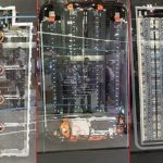
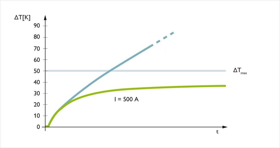
High power charging technology combined with liquid cooling supports charge times comparable to filling up the gas tank on a conventional car or truck. Proposed designs can deliver 500kW of power (500A at 1kV) while still maintaining a low-temperature rise (Figure 3). High-power XFC charging stations using liquid-cooled connectors that conform with the CCS standard will also be backward-compatible with EVs that do not support XFC technology.
Charging heavy-duty vehicles
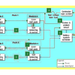
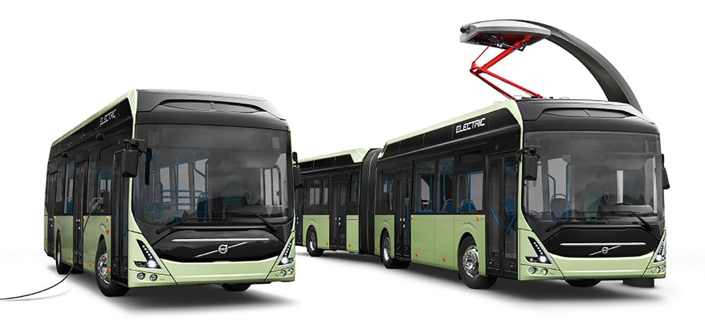
Medium- and heavy-duty vehicle (MHDV) charging systems began with the standard J1772-CCS Type 1 plug-in connector but are increasingly turning to various forms of the SAE J3105 “Electric Vehicle Power Transfer System Using Conductive Automated Connection Devices Recommended Practice.” J-3105 is focused on DC charging buses and other MHDVs and includes general physical, electrical, functional, testing, and performance requirements for connections to vehicles using conductive automated-charging devices (Figure 4). It is designed to ensure safe and reliable charging. It defines a conductive power transfer method, including the curbside electrical contact interface, the vehicle connection interface, the electrical characteristics of the DC supply, and the communication system. It also covers the functional and dimensional requirements for the vehicle and charger connections.
In addition to the general description, there are three sub-sections in J-3105 focused on specific applications:
- J3105-1, Infrastructure-Mounted Cross Rail Connection
- J3105-2, Vehicle-Mounted Pantograph Connection
- J3105-3: Enclosed Pin and Socket Connection
Future MHDV charging systems will be based on higher voltages to support higher power levels. Today’s designs are often based on 480V mains. Next-generation chargers are being developed to operate from 1,200V mains to deliver over 1MW of power.
Opportunity charging
Opportunity charging refers to short, frequent charging of batteries, such as charging of buses or delivery trucks for 3 to 6 minutes during stops. For example, pantograph charging systems use 150V to 850V and deliver up to 600kW, allowing the systems to support various charging needs and vehicle sizes. Opportunity charging for MHDVs enables the vehicles to have a smaller and lower-cost battery pack to support a given driving range.
Opportunity charging can also support longer battery back lives by enabling less depth of discharge. Depth of discharge is an important factor in the cycle life of batteries. Greater depth of discharge shortens cycle life.
In addition to pantograph systems, wireless opportunity charging technology is under development. Wireless chargers can be embedded in parking lots or even roadbeds to charge vehicles as needed. Current opportunity charging schemes are aimed at fleet operations and often include remote diagnostics of the charging system and batteries, and fleet management software. If wireless opportunity charging becomes an established technology for fleets of EVs, it is expected to be expanded to support the charging needs of consumer automobiles and light trucks.
Summary
EV charger connectors have been regionally standardized to support current charging technologies. In the future, AC charging Level 1 and Level 2 connectors are expected to continue to be used. But to get higher-power DC charging to support XFC and other technologies, connector technology needs to change. One proposal being pursued is the addition of liquid cooling in the cable and connector to enable existing DC fast charging connector formats to support higher power levels without overheating. In addition, SAE recently introduced the J3105 standard that defines charging interfaces for heavy-duty vehicles. J3105 not only anticipates charging rates over 1MW is also supports new connection mechanisms, including pantograph, cross rail, and pin-and-socket connections. Pantograph and cross rail connections are expected to support the opportunity charging of large EVs. In addition, wireless charging technologies are being developed for all types of EV charging applications, including opportunity charging.
References
CharIN (Charging Interface Initiative) Association, CharIN
EV Ultra Fast Charger, Gilbarco Veeder-Root
High Power Charging, Phoenix Contact
Liquid Cooling of EV Charging and EV Fleet Operations, Colder Products=
SAE publishes On-Route Mechanized Conductive EV Charging Systems Recommended Practices, SAE International
The Different EV Charging Connector Types, Enel X