Although the electronics industry is relentlessly driven by advances in materials, components, and architectures, the “new” obviously also builds on the “old” and often still uses it, albeit in new guises. There’s still a viable place and need for old devices such as the transformer, solenoid, relay, and Wheatstone bridge. This FAQ will look at the circuit arrangement of this bridge, what it does, why it is still in wide use, and some additional useful variations of it. It’s an excellent example of how a simple and clever configuration not only has many applications but has extended its life into the world of modern electronics.
Q: What is the Wheatstone bridge?
A: In its basic form, it is a passive electrical circuit which is used to measure an unknown electrical resistance by ratiometric balance of legs (sometimes called arms) of a four-element “bridge circuit” with the unknown resistance as one of the legs, Figure 1. The circuit can be used to compare an unknown resistance Rx with others of a known value. It is sometimes drawn as a square, Figure 2 (especially by CAD programs), but most engineers prefer the diamond shape which shows the functionality more clearly.
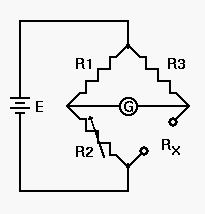
Fig 1: The classic Wheatstone bridge schematic has four elements arranged in a diamond pattern, with an excitation voltage, while the null reading is usually (but not always), taken across the midpoint. (Image source: Play-Hookey.com)

Fig 2: The bridge is sometimes drawn as a rectangle; this is less intuitive than the diamond rendition although it is electrically identical. (Image source: Instructables.com)
Q: Can’t you simply use an ohmmeter to measure resistance?
A: Of course you can. But the bridge is capable of extreme accuracy and precision and allows comparison to high-accuracy standards. Also, it was developed well before any sort of meter as we know it eve existed.
Q: Why is the bridge so good?
A: We’ll get to that soon…first, some background. What we call the Wheatstone Bridge was actually invented by Samuel Hunter Christie (1784-1865) in 1833, but Charles Wheatstone (1802-1875) popularized the arrangement of four resistors, a battery and a galvanometer, along with its many uses; Wheatstone even gave Christie credit in his 1843 Bakerian Lecture, where he received one of these premier medals from the Royal Society to recognize his exceptional and outstanding science efforts (Wheatstone called the circuit a “Differential Resistance Measurer”).
Q: What are the elements of the original Wheatstone bridge?
A: There bridge had the four legs cited: two known, fixed resistors; the unknown resistance, and a wire with a sliding contact which was the precision known resistor used for measurement. By adjusting the slider across the wire, the user could “set” that leg to precise values. There was also a battery and a galvanometer.
Q: What is a galvanometer?
A: It is a highly sensitive instrument for measuring current, but what it excels at is determining when there is zero current flow (a “null”). Although we can now measure current with a digital meter to high precision, the galvanometer is still used for precision measurement and null-current indication.
Q: So how does the bridge function?
A: It is a ratiometric arrangement. The current across the bridge will be at zero when the ratios of the left and right sides are equal. (Note that the values of resistors R1 and R3 are precisely known, but they do not have to be identical.) Resistor R2 is the calibrated variable resistance, and Rx is the unknown resistance. Using basic circuit analysis, it is easy to show that the bridge is balanced (at null, with zero current between the R1/R2 junction and the R3/Rx junction,) when R1/R2 = R3/Rx. To measure an unknown resistance, adjust R2 until the galvanometer reads zero current. At this point, Rx = R2 × R3/R1. Note that the value of the bridge excitation voltage does not appear in the equation — this is a major advantage.
Q: Do all of the resistors need to have the same nominal value?
A: They do not, although that is the most-common implementation. The bridge will be “balanced” with zero current as long as the ratios are equal.
Q: Why use this configuration?
A: First, it’s much easier and precise to detect a null (zero current) than measure the actual value of current, especially in the pre-meter, pre-electronics days. Second, the ratiometric nature of the bridge means that certain internal errors will cancel out, which is always a good thing from an engineering-design perspective.
Q: What are the modes of operation for the Wheatstone bridge?
A: The bridge circuit can be used in one of two ways. The first is to adjust component values until the bridge is balanced, as discussed above. This is typically used to determine the value of an unknown resistor in the bridge when the other three resistances are known. The second method is to measure changes in the output voltage across the bridge when one of the resistances is subject to externally-applied changes of some kind. This approach commonly replaces one resistor with a resistive device that reacts to changes in temperature, pressure, or shape, and is used to monitor and measure such changes.
Q: How would I use the bridge for such a sensor application?
A: Consider a very common situation of a 350Ω strain gauge whose resistance varies very slightly around the nominal value with applied strain (strain is the response of a system to an applied stress). Measuring that small change in resistance directly is difficult due to small signal levels, noise, and other factors. Instead, use a bridge with two 350Ω resistors for the opposing legs, and then adjust the fourth leg’s resistance, so the bridge is at null. Measure that adjustable resistor, and you’ll know the value of the strain gauge.
Alternatively, use the bridge arrangement, but measure the current across the bridge. Calculation based on Ohm’s law will yield the strain gauge’s resistance value versus applied strain.
Q: I still don’t see the cancellation effect, can you explain?
A: Here is where the ratiometric topology is a major virtue. First, as noted before, the bridge excitation voltage does not enter into the bridge equation. Thus, this voltage does not have to be precise or free of noise or ripple. In contrast, if a simple resistive divider was used (Figure 3), the excitation voltage would be a factor.
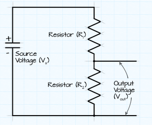
Fig 3: Unlike the bridge arrangement as used for measuring resistance, the voltage across an unknown resistor in a simple voltage divider is a function of the excitation voltage. (Image source: OhmsLawCalculator.com)
Further, almost all sensors (including strain gauges), are also sensitive to temperature, and this would affect the accuracy of the reading. With a bridge arrangement, it’s easy to work around this dilemma: just use another, identical strain gauge for the other arm of the side that has the active gauge but mount it in a strain-free location near the one active one. As the temperature changes, their drifts will track, and the ratio between these two will remain unchanged, and you’ll only see the effects of strain on the measurement gauge. The temperature-induced changes in the two gauges will “drop out” of the balance equation.
Part 2 of this FAQ will look at some more Wheatstone bridge issues and modern use of the bridge.
References
- NASA, “Wheatstone Bridge Circuit”
- Analog Devices, “Bridge-Type Sensor Measurements are Enhanced by Autozeroed Instrumentation Amplifiers with Digitally Programmable Gain and Output Offset”
- Analog Devices, “How to Stay Out of Deep Water when Designing with Bridge Sensors”
- Ohms Law Calculator, “Voltage Divider Calculator”
- Engineers Edge, “Wheatstone Bridge Circuit Equations and Derivations”
- Kenyon College, “Wheatstone Bridges”


Leave a Reply
You must be logged in to post a comment.