Examine a discrete oscillator circuit today and you’ll likely find an operational amplifier with components in a feedback loop that cause the oscillation. In many cases, oscillators implemented with op amps are updated versions of designs that formerly used odd-ball components such as neon bulbs and delay lines to get the required phase shift needed for oscillation. It is interesting to review some of the more widely used old-style oscillators as a way to grasp the fundamentals of oscillator circuits.
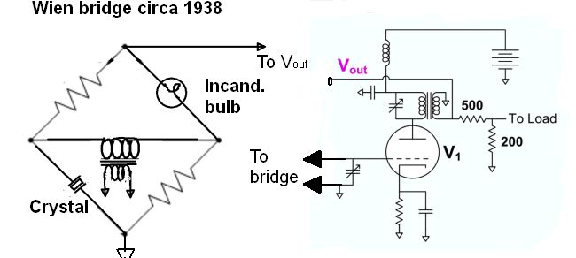
The first oscillator in the odd-ball component category is the Wien bridge oscillator. It originally contained a small incandescent bulb which served as a small electrical resistance. Larned Meacham disclosed the bridge oscillator circuit in 1938 which included a quartz crystal and a lamp in a Wheatstone bridge. The frequency determining components are in the negative feed back branch of the bridge. The gain-controlling elements are in the positive feed back branch. The crystal operates in series resonance and minimizes the negative feedback at resonance. At frequencies below resonance, the crystal is capacitive and the gain of the negative feedback branch has a negative phase shift. At frequencies above resonance, the crystal is inductive and the gain of the negative feedback branch has a positive phase shift. The phase shift goes through zero at the resonant frequency.
The point of the lamp is to serve as a way of reducing gain as the lamp heats up. As the lamp heats up, it reduces the positive feedback. When first powered up, the lamp is cold and has a low resistance. This makes the circuit gain greater than one and helps kick-start the oscillator. As the lamp warms with bigger amplitudes, its resistance rises. This reduces the gain of the circuit and stabilizes the oscillator amplitude.
The lamp exhibits a fair degree of thermal lag. That means its resistance doesn’t change much above audio frequencies, limiting the range of its use. And below about 10 Hz, there is a noticeable distortion on the top of the oscillation waveform compared to the bottom because the bottom of the waveform generates less heat; at low frequencies the bulb cools more compared to the top of the waveform where it generates more heat.
 That brings us to relaxation oscillators, which produce non-sinusoidal waveforms such as sawtooth, triangle and square waveforms. One type of relaxation oscillator is the Pearson-Anson oscillator which incorporates a neon bulb connected across a capacitor. The bulb has nonlinear current-voltage characteristics that allow it to function as a switching device. To understand its operation one must first understand the properties of a neon bulb that make it a candidate for use in oscillator circuits.
The glass bulb contains two electrodes separated by an inert gas such as neon at low pressure. When a voltage is applied across the electrodes, the gas conducts almost no electric current until a threshold (called a firing or breakdown) voltage is reached. At this voltage electrons in the gas knock other electrons off gas atoms, which go on to knock off more electrons in a chain reaction. The gas in the bulb ionizes, starting a glow discharge. As the bulb glows, its resistance drops to a low value.
In its conducting state, the current through the bulb is limited only by the external circuit. The voltage across the bulb drops to a lower voltage called the maintaining voltage. The bulb will continue to conduct current until the applied voltage drops below an extinction voltage which is usually close to the maintaining voltage. Below this voltage, there’s not enough current to keep the gas ionized, so the bulb switches back to its high-resistance, nonconductive state.
The bulb’s “turn on” voltage is higher than its “turn off” voltage, and it is this hysteresis that allows the bulb to function as an oscillator. The hysteresis is due to the fall in voltage with increasing current after breakdown, i.e. the bulb’s negative resistance.
In the Pearson-Anson oscillator circuit, the capacitor is continuously charged by current until the bulb conducts, discharging it again, after which it recharges.

When the supply voltage turns on, the neon bulb is in its high-resistance condition and acts like an open circuit. Current begins to charge the capacitor, and its voltage begins to rise toward the supply voltage. When the voltage across the capacitor reaches the neon bulb’s breakdown voltage, the bulb turns on and its resistance drops to a low value. The charge on the capacitor discharges rapidly through the bulb in a momentary pulse of current. When the voltage drops to the extinction voltage of the bulb, the bulb turns off and the current through it drops to a low level. The capacitor begins to charge again, and the cycle repeats.
The Pearson-Anson circuit thus functions as a low-frequency relaxation oscillator, the capacitor voltage oscillating between the breakdown and extinction voltages of the bulb in a sawtooth wave. The period is proportional to the time constant RC. The neon bulb flashes briefly each time it conducts, so the circuit can serve as a “flasher” circuit.
To make a Pearson-Anson circuit oscillate, the supply voltage must be greater than the bulb breakdown voltage. Otherwise the bulb can never conduct. Most small neon lamps have breakdown voltages between 80 and 150 V. If the supply voltage is close to the breakdown voltage, the capacitor voltage will be in the “tail” of its exponential curve by the time the bulb voltage hits breakdown, so the oscillation frequency depends on the breakdown threshold and supply voltage levels.
The resistor in the circuit must also be within a certain range of values for the circuit to oscillate. The slope of the load line on the neon bulb I-V curve is equal to R. The possible dc operating points of the circuit are where the load line and the neon lamp’s IV curve intersect. For the circuit to be unstable and oscillate, the load line must intersect the IV curve in its negative resistance region where the voltage declines with rising current.
If circuit resistance is too large–of the same order as the “off” leakage resistance of the bulb (usually >100 MΩ)–the load line will cross the IV curve in a region where the current from the supply is so low that the leakage current through the bulb bleeds it off, preventing the capacitor voltage from ever reaching the bulb breakdown voltage, so the bulb never fires. If R is too small, the current will be so large that once the bulb has turned on, the bulb will keep conducting without current from the capacitor, so the bulb will never turn off.
Neon lamps are relatively slow devices because it takes time to ionize and deionize the gas, so the top frequency of the oscillator is about 20 kHz. The breakdown and extinction voltages of neon lamps also can vary between similar parts, and the thresholds also change with temperature, so the frequency of neon lamp oscillators is not particularly stable.
 Finally, there is the Royer oscillator which is a relaxation oscillator that employs a saturable-core transformer. As a quick review, a saturable-core transformer is a special form of inductor where the magnetic core can be deliberately saturated by a dc current in a control winding. Once saturated, the inductance of the saturable reactor drops dramatically. This lower inductive reactance allows more ac current to flow. The ac current is roughly proportional to the dc through the control winding.
In operation, one transistor will turn on and cause a voltage on the transformer’s primary winding. This, in turn, induces voltages in the base windings having polarities that drive the switched-on transistor further into saturation and the other transistor into cut-off. As current flows through the ON transistor and the half of the primary, magnetic flux in the core rises linearly with time. At some point it will approach saturation. Then voltages across all windings will drop to zero and then reverse polarities. This will cause the OFF transistor to conduct and the ON transistor to be in cut-off.
The key to the Royer oscillator is that one transistor conducts thanks to the transformer flux change. As the core starts to saturate, flux rises by less and less. Eventually the flux is steady and the primary current reaches a maximum. Then current drops and the core comes out of saturation. Once the primary current reaches a maximum, transformer EMF goes to zero, and transformer current starts to drop because the transistor starts to lose its base drive. The transformer no longer linearly passes on changes in primary current to its secondaries. With no current flowing, the change of flux reverses, generating a voltage that makes the second transistor begin conducting.
The Royer oscillation frequency is determined by the maximum magnetic flux density, the power supply voltage, and the inductance of the primary winding. Royer oscillators find most of their uses as power inverters, so the usual frequency range is 50 or 60 Hz.

